Do you have a question about the Agrox RTU5015 and is the answer not in the manual?
Details the physical layout and connections of the control unit.
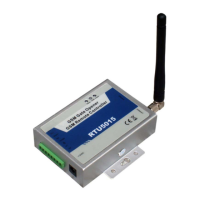
Explains the meaning of various LEDs and interface connections on the device.
Instructions for changing the device's password via SMS command.
Setup, inquiry, and removal of authorized phone numbers.
Commands to enable or disable digital input functions.
Commands to manage access permissions for calling numbers.
Configures the duration the relay remains closed after activation.
Sets the digital input type to NC (Normally Closed) or NO (Normally Open).
Enables SMS confirmation for relay open/close actions.
Customizes SMS alert messages for triggered digital inputs.
Instructions for inserting the GSM SIM card into the control unit.
Guidance on wiring sensors to digital inputs and siren port.
Wiring diagram for connecting the electronic lock or electricity equipment.
Recommendations for placing the mainframe for optimal signal and security.
| Model | RTU5015 |
|---|---|
| Category | Controller |
| Power supply | 12-24V DC |
| GSM frequency | 850/900/1800/1900 MHz |
| Relay Outputs | 2 |
| Protection Class | IP30 |
| Communication Interface | GSM |
| Antenna Interface | SMA |
| Operating Temperature | -20°C to +60°C |
| Relative Humidity | 95% (non-condensing) |
| Digital Outputs | 2 |
| Analog Inputs | No |
| Analog Outputs | 0 |