ESP32-A1S Specification V2.3
Copyright © 2021 Shenzhen Ai-Thinker Technology Co., Ltd All Rights Reserved
6. Design guide
6.1. Antenna layout requirements
(
1
)、
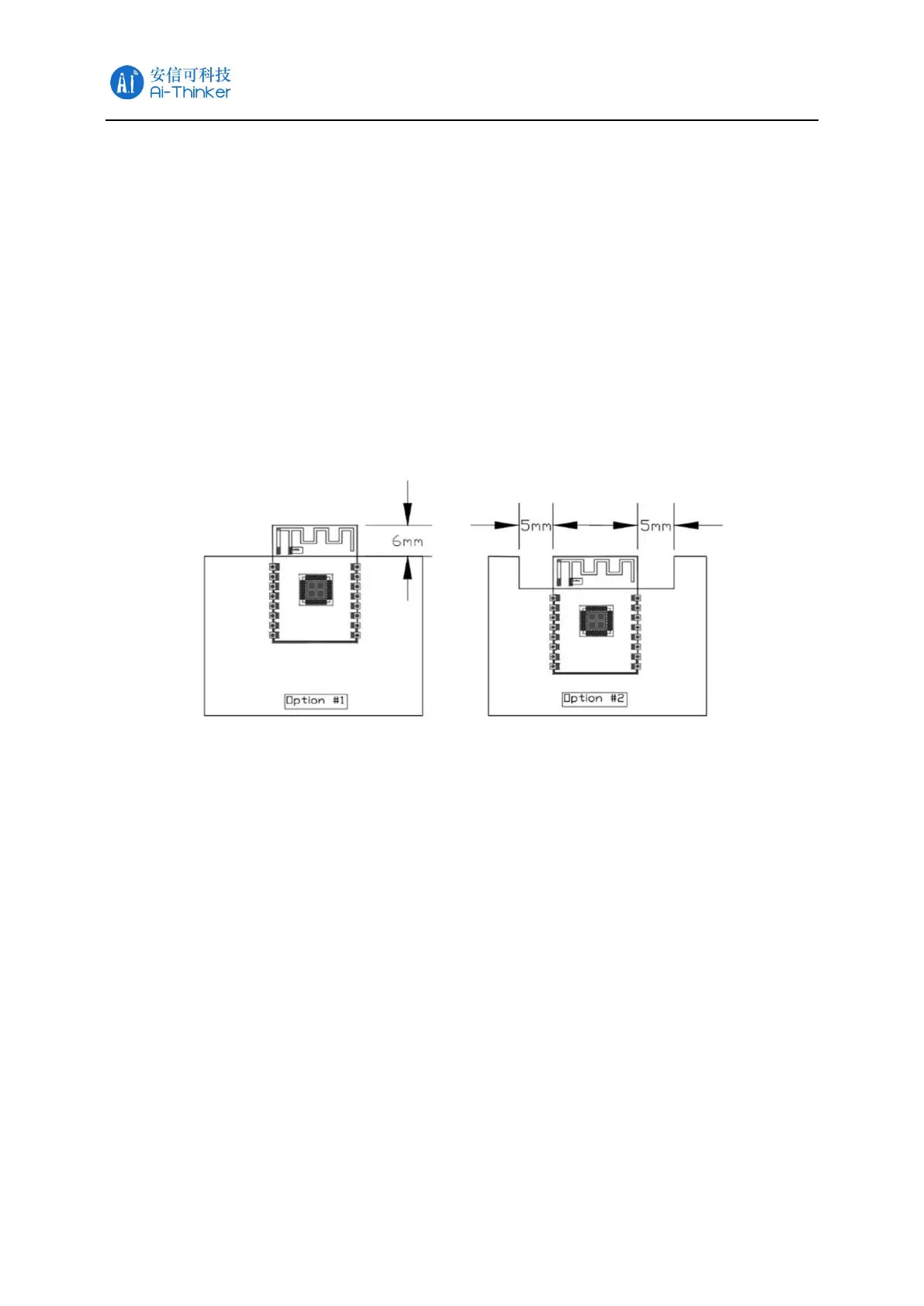
For the installation position on the motherboard, the following two methods are
recommended
:
Solution 1: Put the module on the edge of the main board, and the antenna area
extends out of the edge of the main board.
Solution 2: Put the module on the edge of the motherboard, and hollow out an area at
the antenna position on the edge of the motherboard.
(
2
)、
In order to meet the performance of the on-board antenna, it is forbidden to place
metal parts around the antenna, away from high-frequency components.
Figure 9 Schematic diagram of antenna layout
6.2. Power supply
(1)、Recommend 3.3V voltage, peak current above 500mA
(2)、It is recommended to use LDO for power supply; if DC-DC is used, the ripple is
recommended to be controlled within 30mV.
(3)、It is recommended to reserve the position of the dynamic response capacitor for
the DC-DC power supply circuit to optimize the output ripple when the load changes
greatly.
(4)、It is recommended to add ESD devices to the 3.3V power interface.