40 41
aidacare.com.au
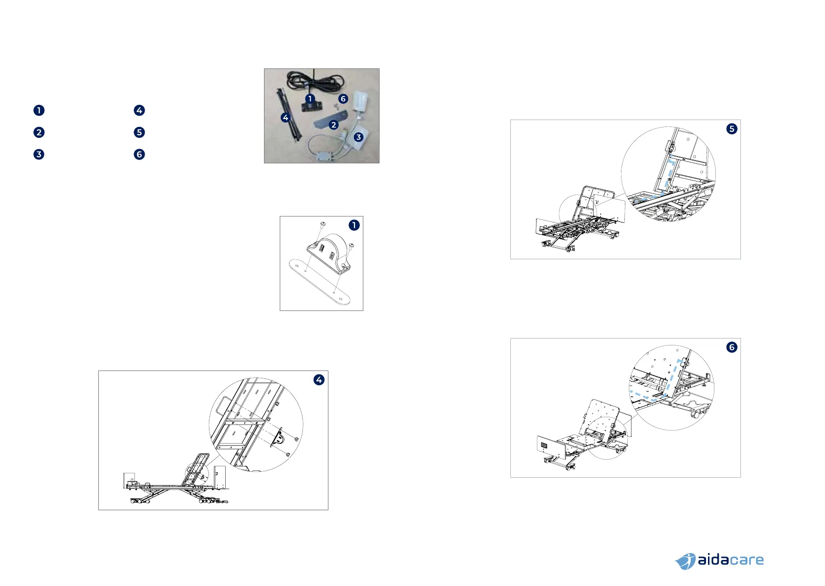
7.10 USB PORT UPGRADE KIT
Carton Contents:
1 x USB Port 10 x Zip ties
1 x Mounting strip
2 x M4 x 16mm screws
(not shown)
1 x Splitter cable 2 x M4 x 8mm screws
Assembly Instructions
NOTE: the USB port can be mounted to either the left or right side of the bed.
The images in this manual are shown for assembly onto the right side of the bed.
1. Mount USB port to the mounting strip using the
provided M4 x 8mm screws. (Only applicable to beds
with serial number prior to FL250-V2-2204-24505)
2. Raise bed to comfortable working height
and the backrest to maximum height
3. Remove the handwheels that secure the mattress
retainer to the backrest but do not remove the
mattress retainer. (Only applicable to beds with
serial number prior to FL250-V2-2204-24505)
4. Assemble USB port to the underside of the backrest using the mattress
retainer legs as studs and secure in place with handwheels (bed serial
number prior to FL250-V2-2204-24505) or using the M4 x 16mm bolts
(bed serial number after FL250-V2-2204-24505)
5. Secure the USB port cable to the backrest along the dashed path shown.
Secure in place using the provided zip-ties which can be slipped in between
the steel tubes and the sheet metal deck as anchoring points. Secure on the
backrest and underneath the middle deck panel.
6. Once the cable is underneath the middle deck, slip it through the gap
between the main structural tube and the deck panel (where the handset
port cable runs through) and lead the cable towards the middle of the bed.
NOTE: Image shown from front for clarity. Cable to be mounted
on the underside of the backrest and mattress deck
 Loading...