Page 14
6.6.2 Four Wire Measurements
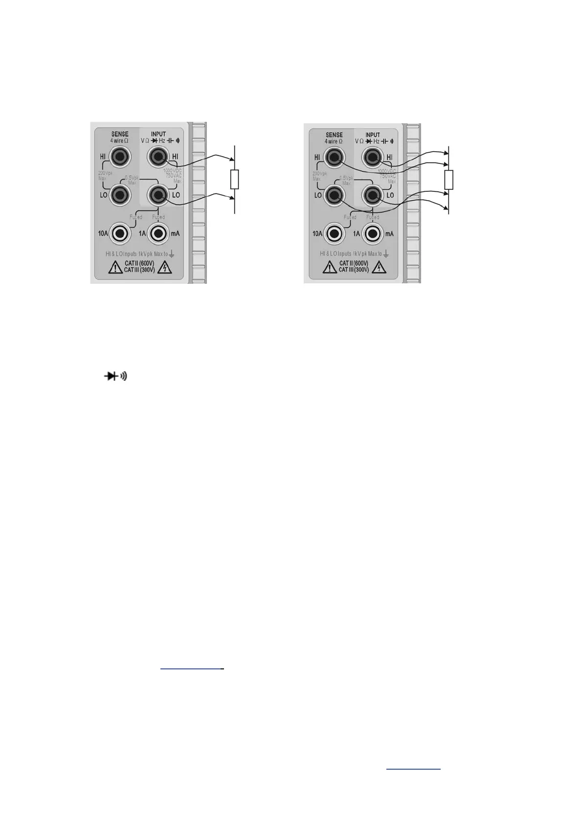
4 wire measurements are appropriate for precision measurement of low resistances where the
effects of the connecting leads and contact resistances are significant. 4 wire measurement
uses the HI and LO SENSE sockets in addition to the HI and LO INPUT sockets.
Connections are made as shown below.
Two Wire Measurement Four Wire Measurement
Because no significant current is flowing through the SENSE connections when utilising 4 wire
measurement, contact resistance does not affect the measurement result.
6.7 Making Continuity and Diode Checks
Pressing []selects either continuity measurement or diode test. Successive presses
alternate between the two as indicated by symbols on the left side of the display. Continuity
and diode checks are made using the INPUT HI and LO sockets within the yellow area of the
panel.
6.7.1 Continuity Measurement
Setting continuity causes the 1000: range to be selected such that readings below
approximately 10: will sound the continuity buzzer. Readings above the range maximum will
show {OPEn}
.
6.7.2 Diode Checks
Setting diode check causes the 1000mV range to be selected and a current of approximately
1mA to flow out of the INPUT HI socket. With the anode of the diode connected to this terminal
the diode forward voltage will be shown. Reverse diode connection will show {OFL}.
6.8 Making Frequency Measurements
Pressing [Hz] selects frequency measurement. Measurements are made using the INPUT HI
and LO sockets within the yellow area of the panel. Four ranges (100Hz to 100kHz) are
available, giving resolutions of 10mHz to 10Hz respectively over an operating frequency range
of <10Hz to 120kHz. Reciprocal counting techniques ensure fast reading updates
(4 readings/second) even on the lowest range. This can be increased to 8 readings/second in
fast speed mode see section 12.2
; however the slow speed mode should always be used when
measuring low frequencies in the 100Hz range to ensure accurate readings.
Measurements are made using the ac Volts input circuitry which is auto-ranged to provide
suitable sensitivity. At low signal levels use a screened lead and an adaptor (BNC to 4mm
plugs, 19mm pitch) to preserve signal quality and avoid spurious readings from stray pick-up.
The minimum measurable signal is <30mV rms across the frequency range (100mV range) or
<10% of range maximum for other ac voltage and current ranges.
Frequency can also be measured in dual measurement mode, see section 8.1.