– 8 –
Wiring Diagrams
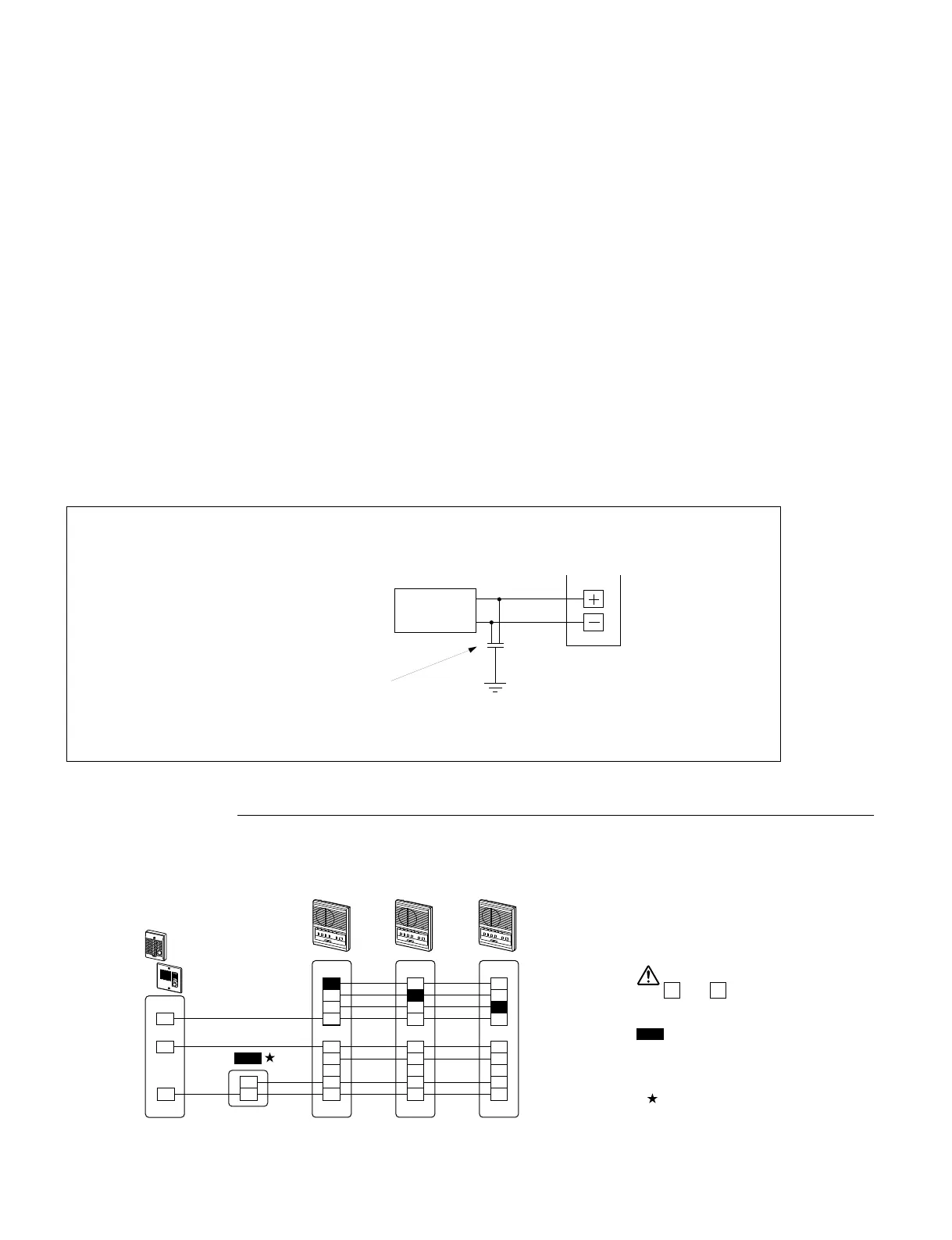
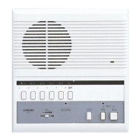
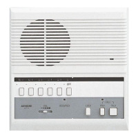
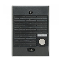
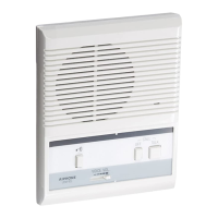
• Three LEF-3 and One Door Station
LEF All-Master configuration
LEF all-master systems are designed to be wired in a looped fashion from the first to last master.
• A single-master system can be wired with 2 conductors homerun from each sub. (Wire #822202 or #821802 in North America)
Cable requirements
Use multi-conductor cable with an overall shield, non-twisted, 0.65mm to 1.0mm (22AWG to 18AWG), to accommodate the
maximum number stations in the system, each of which requires one designated wire, plus up to nine common wires per system,
depending on features used. Selective door release adds one additional wire per door being released. Use the gauge specified
for the maximum distance between the two farthest stations.
Power supply
The entire LEF system can be powered by one power supply (PS-1225UL, PS-1225S, PS-1225, or PS-1215DIN), located near
the center of the wire run.
For a system including the All Call and Chime with the BG-10C, one PS-1225UL, PS-1225S, or PS-1225 will power the BG-10C
and the LEF system.
Surge arrestors
Severe weather conditions, such as lightning storms, may cause damage to LEF equipment.
We recommend that power surge protection be installed as follows: (However, this does not guarantee that no
damage will occur).
• Connect the GROUND terminal of the power supply to an earth ground. In this case, a separate surge arrester is not
necessary.
• When using a power supply that has no GROUND terminal, install a surge arrestor near the output as shown.
• Additional SA-1 surge arrestors can be installed to protect communication lines. One SA-1 per 2 wires on each master station.
Connect 12V DC power supply only.
Do not connect AC.
: PS-1225UL
PS-1225S
PS-1225
PS-1215DIN
PS12
3
C
R
Y
+
–
+
–
–
2
E
R
Y
+
–
LEF-3 #1 LEF-3 #2
1
E
1
3
1
C
2
E
R
Y
+
–
LEF-3 #3
C
1
2
3
E
PS12
Note: This diagram assigns the master
stations as station 1, 2, and 3. The door
station is answered on each station's own
channel button (1, 2, or 3 respectively).
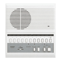
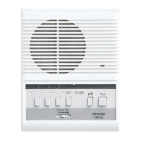
LE-D or LE-DA
PS-1225UL
PS-1225S
PS-1225
PS-1215DIN
LEF model
12V DC
Surge-
arrestor
(Aiphone model SA-1)
Install a surge-arrestor
(discharging voltage: 100~180V)
at a location closest to the unit,
taken to earth ground.
Grounded
Remove the shorting link between
E
and
-
terminals at all the LEF
masters and door/sub stations.