10
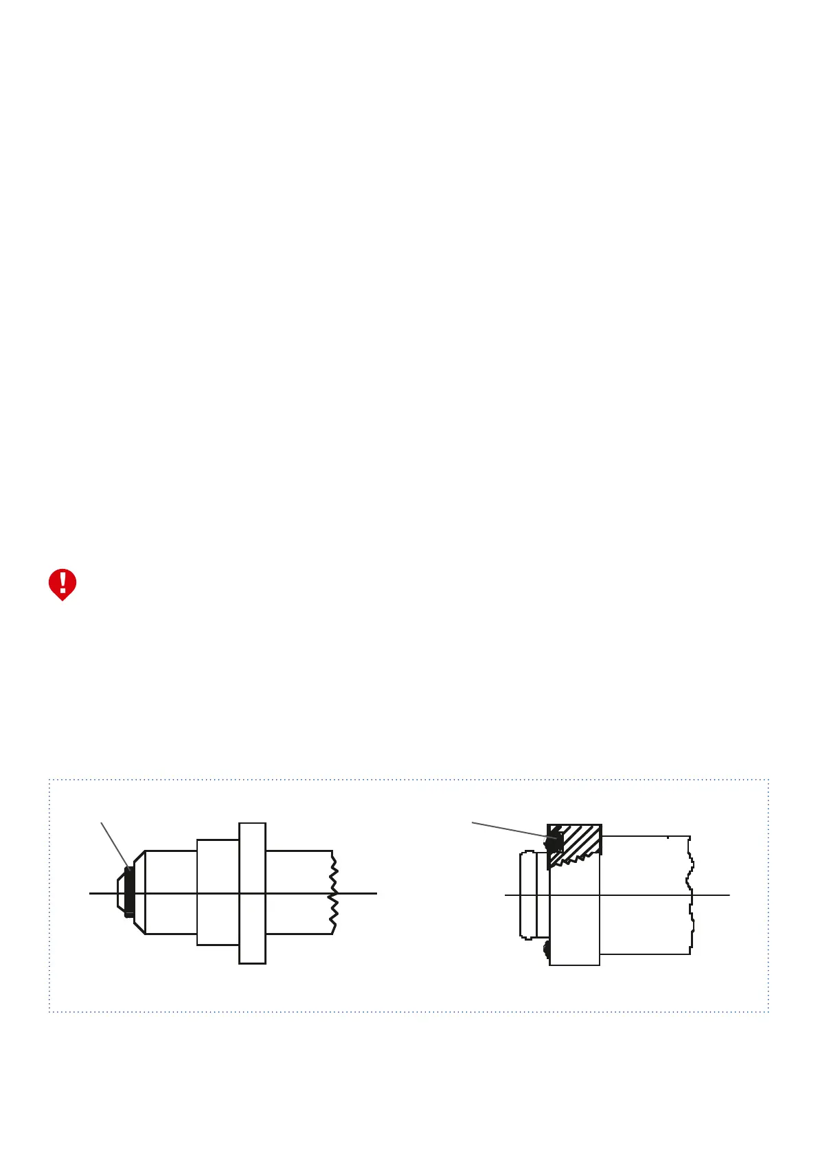
6.1.6 Check connection threads and connection surfaces
of the cylinder valves and the gaskets for proper con-
ditionandfit(seeFig.8.10 / 8.11).MountFlexible
hoses / pigtailswithhandconnection(Oringseal)
without tools on the cylinder valve. Before connecting
theflexiblehose / pigtail,brieflyopenthecylinder
valve once and then close it again, to blow out any dirt
particles that may be present. Do not stand in front of
the outlet opening of the of the valve (7) and make
sure that no danger arises from the escaping gas.
Good ventilation must be provided. Do not blow out
flammable, corrosive, toxic and irritant gases.
6.1.7 At the outlet of the pressure regulator (12), the orifice
plate included in the scope of delivery or optionally
supplied must be inserted or mounted, depending on
the type of gas.
Adapt the outlet to the pipeline by using a compres-
sion fitting. Shortly after the outlet of the pressure
regulator (12), a main line shut-off valve and, if neces-
sary, a safety valve should be installed in the pipeline.
6.1.8 When toxic or flammable gases are used, safe dis-
charge of the purge gas must be ensured. The exhaust
gas pipes must be connected to the outlet connection
of the blow-off valve on the pressure regulator (3 or 8)
and to the purging valves (1) by using compression
fittings.
6.1.9 After successful installation, the system must be purged
with dry inert gas of suitable quality (e.g. nitrogen). All
detachable connections must be leak tight. The tight-
ness test must be certified and checked repeatedly at
regular intervals.
6.1 Assembly
6.1.1 Assembly may only be carried out by persons who are
trained, experienced in the field of application (gas
installations) and have been instructed in safety tech-
nology. The trainings and instructions must be carried
out in regular intervals.
6.1.2 The pressure manifolds shall be supplied pre-assem-
bled as far as possible. Check scope of delivery in
accordance with the datasheet. Check on the basis of
the type plate whether the station is suitable for the
intended use (pressure, gas type, material).
6.1.3 Determine the dimensions of the drill holes according
to the data sheet and fasten the base plate with ap-
propriate screws.
6.1.4 The Cylinder brackets must be fixed on a Wall or similar.
The support must be sufficient to prevent the Cylinder
from falling down. When doing this the outer edges of
the base plate should be vertical and approx. 3/4 of
thecylinderheight(foracylinderheightof1500 mm,
thisisapprox.1100 mm)ashorizontalorientation.
6.1.5 Hose lines / spiral tubes (5) via adapter / check valve
or check valve with filter (antiflapping). First screw the
adapter / check valve into the station inlet first.
The tool must only be applied to the narrow hexagonal.
Then mount the hose line / spiral pipe on the check valve
while holding it against the fitting body with a second wrench.
6 Installation
O-Ring O-Ring
Abb. 8.10 300 bar Abb. 8.11 200 bar