8
GB
IMAT PT- E
6.2) DISASSEMBLY
When disassembly of actuator is required for maintenance,
firstly remove the actuator from the valve. Before performing
any disassembly operations it is important to verify that the
actuator is not pressurised.
Always use caution and double check that the ports 2 and
4 are vented and are free from any accessory and/or device.
When the actuator is a spring return unit, make sure that the
actuator is in the failed position and with pistons completely
inwards before disassembling.
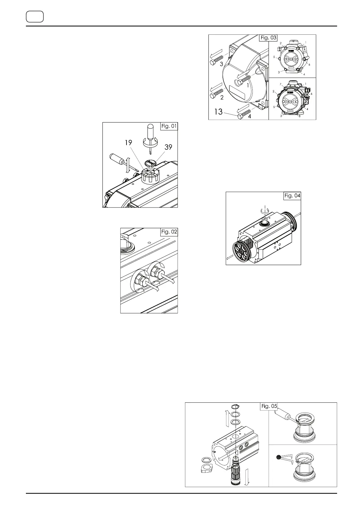
A) Removal of position indicator (Part N° 19), figure 01:
• Remove cap screw (39,
39.1, 39.2) if fitted.
• Lift position indicator
(19) off shaft, it may be
necessary to pry gently
with a screwdriver.
B) Removal of stop cap screws (Part N° 02), figure 02:
• Remove both stop cap screws
together with nut (04) and
washer (03).
• Remove stop screw o-rings
(11) and discard if replacing all
soft parts.
C) End caps disassembly (Part N° 30), figure 03:
• End caps disassembly for spring return actuators (disas-
semble one end cap at a time).
Unscrew the end cap bolts (13) in the sequence shown
in figure 03, until the end-caps are free from springs force
(for PT045 and PT050 N 20-23 turns of the screws, for
PT100 to PT800 4-5 turns of the screws).
Then completely unscrew the screws and remove the
end-cap and the springs.
If there is still force on the end-caps after unscrewing as
indicated above, this may indicate that spring cartridge is
damaged or that the pistons are not completely closed,
so any further disassembly should be discontinued. Fur-
ther disassembly of the end caps may result in injury.
• End caps disassembly for double acting actuators (dis-
assemble one end cap at a time)
Unscrew the end cap bolts (13) in the sequence shown
in figure 03, until the screws are completely unscrewed
and the end caps are free.
• Remove the o-rings (14) using a screwdriver. Discard
soft parts if replacing.
• Only for actuators with adjustment 50% or 100%, re-
move the nut 04R, the washers 03R and o-rings 11R
and discard soft parts if replacing.
D) Pistons disassembly (Part N° 40), figure 04:
• Holding the body (50) in a vice or similar device, rotate
the drive shaft (60) until the pistons (40) are released.
Caution: air pressure should not be used to remove the
pistons from the body.
• Remove o-rings (16) using a screwdriver. Remove the
piston back (05) and piston head (15) bearings.
• Discard bearings when replacing all soft components.
E) Drive shaft disassembly (Part N° 60), figure 05:
• Remove the spring clip (18) using snap-ring pliers or
screwdriver for spiral rings, remove the thrust washer
(10) and the external thrust bearing (08). Apply down-
ward force to top of drive shaft (60), until it is partially
out of the bottom of the body when it is possible to re-
move the internal thrust bearing (08) and the octi-cam
(01), then push the pinion (60) completely out of the
body. If pinion is not easily removed, gently tap the top
of the shaft with a plastic hammer.
• Remove top (06) and bottom (07) pinion bearings and
top (20) and bottom (21) pinion o-rings.
• Discard bearings (06) and (07), internal and external
thrust washer (08) and o-rings (20) and (21) if replacing
the soft components.
All the components disassembled and not replaced will
have to be cleaned and inspected for wear and before
reassembly, if necessary, also replace the plugs (09).
 Loading...