AirSense Model 310e Operator’s Manual
Installation
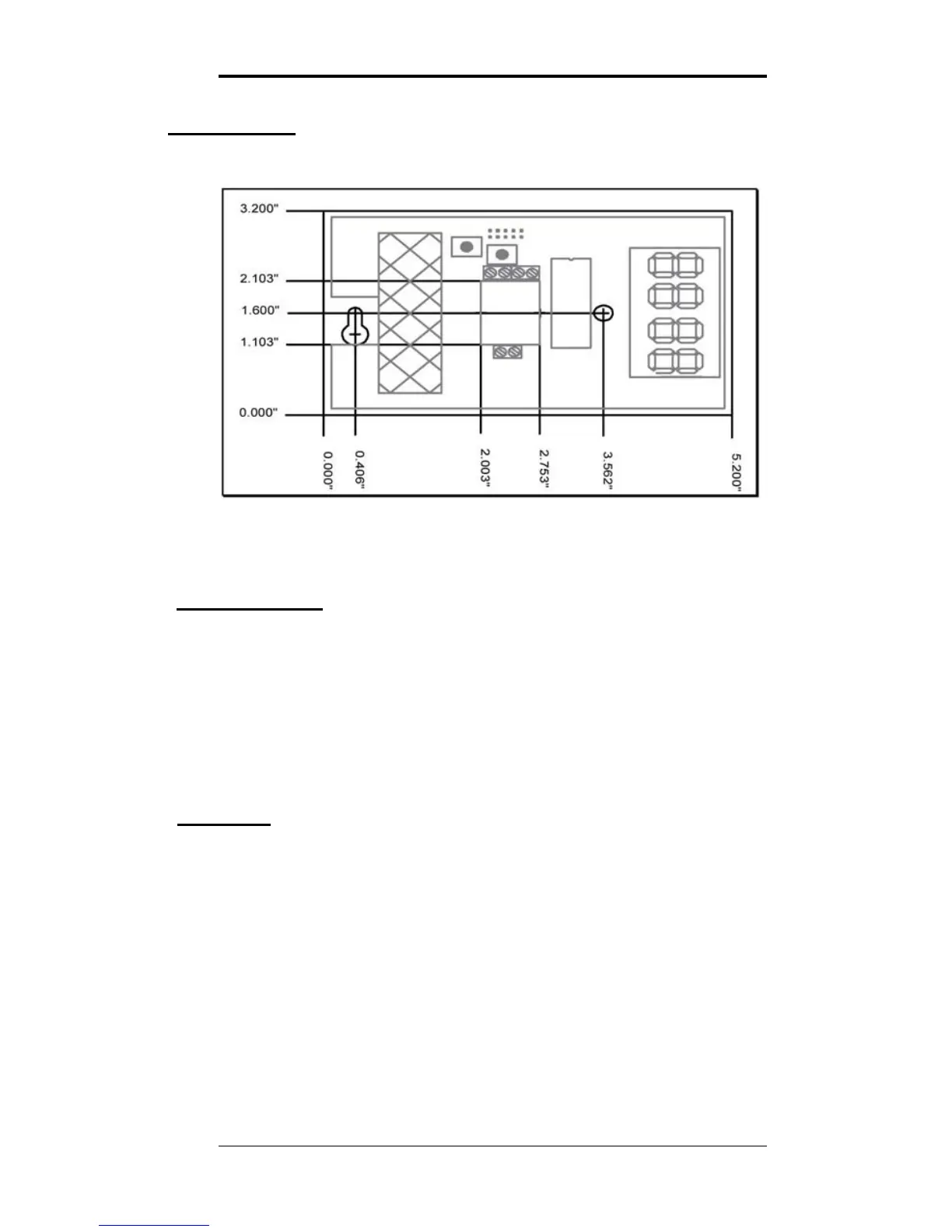
Figure 1: AirSense Model 310e Mounting Dimensions
Cover Removal
To open the Model 310e use a coin in the slot on the bottom
to release the snap. Lift the cover up slightly to disengage
the closure and remove cover with a downward motion to
clear the catch at the top of the unit.
The locations of controls and terminals on the main circuit
board are shown in the Figure 2 on page 4.
Mounting
The Model 310e is designed for flush mounting with two
fasteners. The locations of the mounting points (shown in
Figure 1) allow direct mounting on a standard simplex
(single circuit) junction box. There is a wiring cutout in the
center of the unit near the terminal strips.
3/9/15 Digital Control Systems Page: 3