AirSense Model 310e Operator’s Manual
Wiring
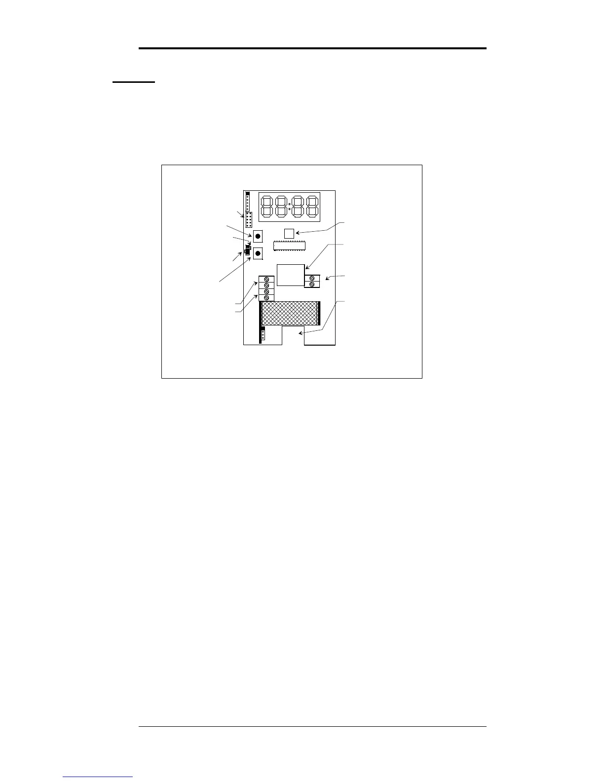
This section describes the external connections to the Model
310e. Wiring enters the chassis through the cutout in the
center of the unit.
SHORTING BLOCK HERE
FOR VOLTAGE OUTPUT
USER
JUMPERS
UP
BUTTON
DOWN
BUTTON
ANALOG OUTPUT
SELECTOR
RELAY CONNECTION
SHORTING BLOCK HERE
FOR CURRENT OUTPUT
UPPER MOUNTING
SCREW ACCESS
ANALOG OUTPUT
+
OUT
-
DIS1
J3
JP3
JP2
JP1
JP4
JP5
+
-
WIRING
ACCESS
POWER IN
(POLARITY MATTERS
FOR DC INPUT ONLY)
LOWER MOUNTING
SCREW ACCESS
MICROPROCESSOR
J4
J5
POWER
J8
+
-
DN
UP
Figure 2: Model 310e Component Locations
Power Supply
The Model 310e will operate from an AC or DC input
voltage between the values called out in the specifications on
page 2. The power supply leads are connected to the two-
terminal power connector shown in Figure 2.
The model 310e must never be connected directly to line
power. Operation at voltages higher than specified will
damage the unit and void the warranty.
When operating from DC power, the polarity of the power
leads must be as shown in Figure 2. Reversed polarity
connection will not damage the unit, but will make it
inoperable until the connection is reversed.
Signal Output
The Model 310e provides either a 0 - 10 volt or a 4 - 20 mA
current loop output at the two terminals of the analog output
connector shown in Figure 2.
3/9/15 Digital Control Systems Page: 4