6
Exterior
Flying Cloud 6-5
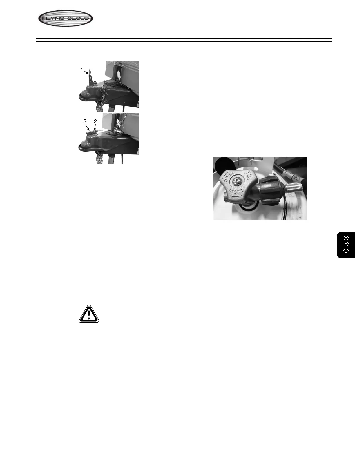
Hitch/Coupler
1. Open Position
2. Padlock Insert Hole
3. Closed Position
Operating Instructions
1. To open - slide forward and pull up to open latch
before inserting ball.
2. Place coupler on ball of same diameter as coupler
and of same or greater capacity.
3. When ball is completely nested in socket, push
top of latch handle rearward until handle snaps
into closed position. Extend jack to ground and lift
tow vehicle/trailer combination 2 to 4 in. to ensure
coupler is securely attached to tow ball. Retract
jack before towing.
4. Insert padlock through hole in handle for theft-
prevention purposes.
WARnInG
Always open latch handle before inserting ball into
coupler.
Liquid Petroleum Gas (LPG)
note
Refer to Section 2 - Safety and Section 5 -
Interior for additional LPG warnings and safety
information.
Fill Valve
The LPG tanks are equipped with ll valve connections
RV Type I Acme. The large, green, nylon swivel nut is
a right-hand thread and is designed for hand operation
only.
The valve features an internal spring-loaded module
that will not allow gas to ow from the cylinder until a
positive seal has been made at the connection. The
valve outlet has 1-5/16 in. Acme threads on the outlet
exterior, and female POL, left-handed threads on its
interior. This feature allows for connection of the new
wrenchless, right-handed, Acme RV connection while
still accommodating the standard left-handed POL
ttings used for lling propane cylinders.
The mating, green swivel nut and brass nipple also
incorporate new features: the green nylon nut swivels
on a black bushing that is heat-sensitive. Between 240
and 300°F, the bushing will yield (melt) allowing the
spring-loaded module in the valve to push the brass
nipple back (approximately 1/4 in.), closing the module
and stopping the ow of gas from the cylinder. Inside
the brass nipple is a ow-limiting device designed
to sense excessive gas ow. If an excessive ow is
sensed, the ow-limiting device shuts the ow down
to a maximum of 10 SCFH (Standard Cubic Feet per
Hour) or less. This is also referred to as the bypass
ow.
Bypass ow is extremely important in the proper
operation of this connection. The ow-limiting device
may activate if the cylinder valve is opened quickly.
When all appliances are off, the bypass ow allows
the pressure downstream from the ow-limiting device
to equalize. When pressure is equalized, the ow-
limiting device will supply normal ow to the system.
Equalization occurs in approximately 5 seconds and,
in most cases, goes completely unnoticed. If, however,
an appliance is left on or there is a leak or open ow
in the system, the bypass pressure will not be able to