EasyManua.ls Logo

Airwell AQL20-75 - User Manual

Airwell AQL20-75
76 pages
Print Icon
To Next Page IconTo Next Page
Loading...
English Deutsch EspañolItalianoFrançais
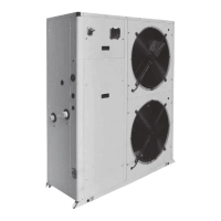
Air Cooled Water Chillers and Heat Pumps
Refroidisseurs de liquide à condensation par air et pompes à chaleur air-eau
Luftgekühlte Flüssigkeitskühler und Wärmepumpen
Refrigeratori d'Acqua e Pompe di Calore Raffreddati ad Aria
Enfriadores de Agua y Bomba de Calor Condensadas con Aire
Installation and maintenance manual
Manuel d'installation et de maintenance
Installations- und Wartungshandbuch
Manuale di installazione e di manutenzione
Manual de instalación y de mantenimiento
AQL/AQH 20-75
AQC 40-75
IOM AQ410-N.3GB
Part number / Code / Code / Codice / Código : 035B09040-000D
Supersedes / Annule et remplace / Annulliert und ersetzt / Annulla e sostituisce /
Anula y sustituye : 035B09040-000C
Notified Body / Organisme Notifié / Benannte Zertifizierungsstelle / Organismo
Notificato / Organismo Notificado N°. 1115
20
77 kW
20
86 kW
ISO 9001 certified management system

Table of Contents

Questions and Answers

  • K
    Kim ChapmanAug 17, 2025
    Why is my Airwell AQL20-75 Heat Pump making excessive noise?
    • M
      Mark RogersAug 17, 2025
      Excessive noise in your Airwell Heat Pump can stem from several sources. Check the clamping brackets of the lines for vibration. If the thermostatic expansion valve emits a whistler, refill. Inspect the dehydrating filter and ensure the compressor’s locknuts are tightened. If the compressor is noisy with seized bearings, it will need to be replaced.
  • G
    Gail TaylorAug 20, 2025
    What to do if the HP alarm activates and stops my Airwell AQL20-75 Heat Pump?
    • M
      Mark SanchezAug 20, 2025
      If the HP alarm activates and stops your Airwell Heat Pump, it could be due to several reasons. Check the operation of the pressure switch and replace it if defective. Ensure the delivery valve is fully open; replace it if it’s faulty. If there are substances with condensable gases in the circuit, drain the circuit. Also, verify that the condenser fan is functioning correctly by checking its cables and motor; repair or replace if defective.
  • J
    Jonathan BoydAug 25, 2025
    Why is my Airwell AQL20-75 Heat Pump running but not cooling?
    • P
      Pamela MedinaAug 25, 2025
      If your Airwell Heat Pump is running but not cooling, it could be due to an insufficient charge of refrigerant, in which case, you should refill it. Alternatively, the dehydrating filter might be clogged and needs replacement.
  • M
    Melanie BarnesAug 27, 2025
    What causes a low oil level in the Airwell Heat Pump compressor?
    • A
      Andrea WarrenAug 27, 2025
      A low oil level in your Airwell Heat Pump's compressor can be caused by one or more gas or oil leaks in the circuit; identify and remove these leaks. It can also be due to a mechanical failure of the compressor, or an anomaly of the oil heater of the compressor’s base. If the latter, check the electric circuit and the resistor of the heater of the motor base, and replace defective components.
  • D
    David RobinsonAug 30, 2025
    What causes the LP alarm to activate and stop the Airwell AQL20-75 Heat Pump?
    • P
      pmorrisAug 30, 2025
      The activation of the LP alarm, which stops the Airwell Heat Pump, can be due to a gas leak (identify and remove the leak) or an insufficient charge of refrigerant (refill).
  • C
    Catherine WoodSep 3, 2025
    How to fix ice on the suction line of my Airwell AQL20-75?
    • J
      Justin ParkerSep 3, 2025
      Ice forming on the suction line of your Airwell Heat Pump can be due to wrong calibration of overheating (increase overheating) or due to charge (check the charge).
  • M
    mgriffinSep 6, 2025
    What causes frosting of the liquid line in my Airwell AQL20-75?
    • C
      christopher54Sep 6, 2025
      Frosting on the liquid line of your Airwell Heat Pump can occur if the valve of the liquid line is partially closed; check that the valves are open. Another cause could be a clogged liquid filter; replace the cartridge or the filter.
  • A
    Annette CastroSep 9, 2025
    Why is the liquid line of my Airwell AQL20-75 too hot?
    • M
      morganlopezSep 9, 2025
      If the liquid line of your Airwell Heat Pump is too hot, it's likely due to an insufficient charge. Identify and remove the cause of the loss of charge and refill.
  • Y
    yperryNov 13, 2025
    What to do if one or both Airwell AQL20-75 compressors are not working?
    • R
      Robert TaylorNov 13, 2025
      If one or both of your Airwell Heat Pump compressors aren't working, several issues could be the cause. First, check the electric circuit for ground dispersions and short circuits, and inspect the fuses. Also, examine the wiring of check and safety devices. Ensure that the terminals are not loosened and tightened properly. If the HP pressure switch has intervened, reset it along with the control panel, then restart the appliance, making sure to identify and remove the cause that enabled the pressure switch. If a thermal overload has halted the electric circuit, check the operation of check and safety devices and identify and remove the cause. Also, check the line voltage; if it's too low, address system problems or inform the Energy Distributor if the issue stems from the distribution netw...

Summary

Foreword

Introduction to the Manual

Provides an overview of the unit's purpose and manual, including symbols and conventions.

Warranty Information

Outlines warranty conditions, validity requirements, and responsibilities.

Emergency and Normal Stop Procedures

Explains how to safely stop and restart the unit using control panel functions.

Manual Structure and Conventions

Describes the symbols and conventions used throughout the manual for clarity.

Safety Guidelines

Safety Foreword and Definitions

Introduces safety regulations and defines key terms like Owner, Installer, and Operator.

General Safety Precautions

Lists general safety guidelines for operating and approaching the unit.

Precautions Against Residual Risks

Details precautions for control, mechanical, and electrical residual risks.

Maintenance Safety Precautions

Outlines essential safety measures for performing maintenance operations.

Identification of Safety Labels

Identifies various safety labels and their meanings on the unit.

Refrigerant Safety Regulations

Covers safety data and regulations for refrigerants and lubricants.

Transport, Handling, and Storage

Unit Inspection Upon Receipt

Instructions for inspecting the unit upon receipt for damage and completeness.

Safe Handling Procedures

Guidelines for safely lifting and moving the unit using appropriate equipment.

Anchoring and Securing the Unit

Explains when and how to secure the unit to its installation site.

Storage Recommendations

Provides precautions for storing the unit before installation to prevent damage.

Installation Guide

Selecting the Installation Site

Details requirements for selecting an appropriate installation location for the unit.

External Water Circuit Setup

Describes the necessary components and considerations for the external water circuit.

Water Connections Procedure

Instructions for connecting the water lines to the unit's inlet and outlet.

Defrost Water Drainage (Heat Pumps)

Specifies drainage requirements for heat pump units during defrost cycles.

Water Buffer Tank System

Details the water buffer tank, its features, components, and installation.

Power Supply Requirements

Details the requirements for connecting the unit to the electrical power supply.

Electrical Connections Guide

Explains how to perform electrical connections according to diagrams and standards.

Unit Start-Up Procedure

Preliminary Checks Before Start-Up

Lists essential checks to perform before the unit's initial start-up.

Step-by-Step Start-Up Sequence

Provides the procedure for safely starting the unit for the first time.

Operational Checks After Start-Up

Outlines checks to ensure proper operation after start-up.

Customer Handover and Training

Instructions for training the end-user on unit operation.

AQL;AQH Control System

Electronic Card Control and Interface

Describes the electronic control unit, keyboard, and display interface.

DIP Switch Settings

Explains the function and settings of the DIP switches for unit configuration.

Alarm and Log Menu Functions

Details alarm codes, descriptions, and how to view logged alarms.

Sensor Reading (SEnS Menu)

Lists sensor codes and their meanings for reading operational data.

SIF Fan Configuration

Explains how to configure special inverter fans for specific static pressure.

AQC Control System

AQC Control System Overview

Introduces the microprocessor control system for AQC units with 2 compressors.

Control Display Functionality

Describes the LCD display and its information presentation.

Control Keyboard Operation

Explains the function of the keyboard keys for navigating and setting parameters.

Alarm Codes and Descriptions

Lists alarm codes, their descriptions, and operational status.

Product Description

General Unit Information

Provides a general description of the AQL/AQH units, their purpose, and construction.

Accessories for AQL;AQH 20-35

Details optional accessories available for AQL/AQH 20-35 models.

Accessories for AQL;AQH 40-75

Details optional accessories available for AQL/AQH 40-75 models.

Refrigerant Flow Diagrams

Illustrates the refrigerant flow within the various AQL/AQH/AQC unit configurations.

Technical Data

Hydraulic Features and Curves

Presents hydraulic performance curves for water flow and pressure drop.

Physical Specifications

Lists physical specifications for different unit models including dimensions and weight.

Electrical Specifications

Provides detailed electrical specifications for various unit configurations.

Shock Absorber Mounting Positions

Shows shock absorber positions and weight distribution for installation.

Dimensional Drawings of Units

Presents detailed dimensional drawings for different unit series.

Installation Space Requirements

Specifies the required clearances for unit installation and ventilation.

Maintenance Procedures

General Maintenance Requirements

Outlines general requirements for unit maintenance and service.

Planned Maintenance Schedule

Details the planned maintenance schedule and required checks.

Refrigerant Charge Procedure

Explains the procedure for charging the refrigerant circuit safely and correctly.

Compressor Maintenance

Provides information regarding compressor maintenance and oil requirements.

Condenser Cleaning

Describes how to clean the condenser coils and potential issues.

Fan System Maintenance

Information on the condenser fans and their maintenance.

Dehydrating Filter Maintenance

Explains the function and maintenance of the dehydrating filter.

Sight Glass Inspection

Describes how to use the sight glass to check refrigerant and humidity.

Thermostatic Expansion Valve Adjustment

Details the procedure for checking and adjusting the thermostatic expansion valve.

Evaporator Heat Exchanger Check

Instructions for checking and cleaning the evaporator heat exchanger.

Troubleshooting Guide

Spare Parts and Diagrams

Recommended Spare Part List

Lists recommended spare parts for the unit's first two years of operation.

Compressor Lubricant Oil

Specifies the type of oil used for compressor lubrication.

Location of Wiring Diagrams

Indicates where wiring diagrams are located and how to request them.

Dismantling and Disposal

General Dismantling and Disposal Procedures

Provides general guidelines for safely dismantling and disposing of the unit.

Airwell AQL20-75 Specifications

General IconGeneral
BrandAirwell
ModelAQL20-75
CategoryHeat Pump
LanguageEnglish

Related product manuals