J
Jennifer Moore DDSAug 19, 2025
Why is my Airwell AQH 20-75 making excessive noise?
- HHolly NguyenAug 19, 2025
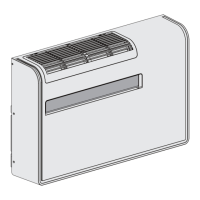
Excessive noise in your Airwell Heat Pump can stem from several sources. Check the clamping brackets of the lines for vibration. If the thermostatic expansion valve emits a whistler, refill. Inspect the dehydrating filter and ensure the compressor’s locknuts are tightened. If the compressor is noisy with seized bearings, it will need to be replaced.