EasyManua.ls Logo

Airwell XLM12 User Manual

Airwell XLM12
30 pages
To Next Page IconTo Next Page
Page #1 background imageLoading...
Page #1 background image
Installation and maintenance manual
Notice d’installation et de maintenance
Installations und Wartungshandbuch
Manuale di installazione e di manutanzione
Manual de instalacion y de mantenimiento
XLM9 XLM 12
SX9 SX12
K9 K11
XLS9 XLS12
GTW11
TH 3939 - Part number / Code / Code / Codice / Código : 3990189
Supersedes / Annule et remplace / annulliert und ersezt /
Annulla e sostituisce / anula y sustituye : TH2790 - 399405
TRIO HIGH TECH
MULTISPLITS
SIMULTANEOUS COOLING - HEATING
FROID – CHAUD SIMULTANE
GLEICHZEITIGER HEIZ UND KÜHLBETRIEB
FREDDO – CALDO SIMULTANEI
FRÍO – CALOR SIMULTÁNEO
7.5 0kW
7.06kW

Table of Contents

Question and Answer IconNeed help?

Do you have a question about the Airwell XLM12 and is the answer not in the manual?

Airwell XLM12 Specifications

General IconGeneral
BrandAirwell
ModelXLM12
CategoryHeat Pump
LanguageEnglish

Summary

Multisplits Trio High Tech

Installation Instructions

General Recommendations

Safety Advice and Warnings

Crucial safety instructions for installation and maintenance work, emphasizing power cutoff.

Outdoor Unit Description

Pipe Connections

Refrigeration Pipe Connections: TRIO and ST

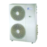
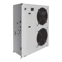
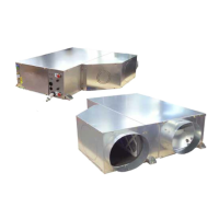
Details on connecting refrigeration pipes between the TRIO outdoor unit and indoor (ST) units.

On-Site Pipe Work Procedures

Guidelines for pipe work performed at the installation site, including brazing and vacuum draining.

Refrigerant Pipe Connections

Indoor Units to Outdoor Unit Connections

Connecting refrigerant pipes between indoor units and the TRIO outdoor unit, including valve tightening.

Refrigerant Charge and Addition

Vacuum Draining Procedure

Wiring Diagram and Legend

Wiring Diagram Legend Details

Electrical Connections

Indoor Unit Installation

Safety: Disconnect Power Cables

Critical safety instruction to disconnect power harnesses before any work on indoor units.

Schematic Diagram (No Electrical Heating)

Schematic Diagram (With Electrical Heating)

Fuse Holder Connection Details

Regulation System

Pre-Start Checks and Final Tasks

Maintenance and Servicing

Related product manuals