
Z
zgrossSep 23, 2025
What does it mean if the LED defrost flashes slowly on my Airwell Air Conditioner?
- NNancy WashingtonSep 23, 2025
If your Airwell Air Conditioner experiences an EEPROM error, the LED defrost indicator will flash slowly.
What does it mean if the LED defrost flashes slowly on my Airwell Air Conditioner?
If your Airwell Air Conditioner experiences an EEPROM error, the LED defrost indicator will flash slowly.
What does E5 mean on my Airwell AW-FWDB018-N91 Air Conditioner?
The error code 'E5' on your Airwell Air Conditioner means there is an issue with communication between the indoor unit and the wired controller.
Why is my Airwell Air Conditioner showing P2?
If your Airwell Air Conditioner is showing 'P2', it means the condenser temperature T3 is too high, triggering a protection mechanism.
What does E1 mean on my Airwell Air Conditioner?
The 'E1' error code on your Airwell Air Conditioner indicates that the outdoor discharge temperature is too high, which has activated a protection.
What does P1 mean on my Airwell Air Conditioner?
The error code 'P1' on your Airwell Air Conditioner indicates an error with the condenser temperature T3 sensor.
What does PE mean on my Airwell AW-FWDB018-N91 Air Conditioner?
The 'PE' error code on your Airwell Air Conditioner indicates Inverter IPM protection has been activated.
What does PA mean on my Airwell Air Conditioner?
The 'PA' error code on your Airwell Air Conditioner indicates DC side over-current.
What does L1 mean on my Airwell AW-FWDB018-N91 Air Conditioner?
The error code 'L1' on your Airwell Air Conditioner indicates a mode conflict.
What does error code E9 mean on Airwell AW-FWDB018-N91 Air Conditioner?
The error code 'E9' on your Airwell Air Conditioner indicates a discharge temperature T5 sensor error.
What does E7 mean on my Airwell Air Conditioner display?
The error code 'E7' on your Airwell Air Conditioner indicates that the indoor fan motor speed has lost protection.
Lists specific model names, dimensions, and power supply details for units.
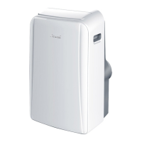
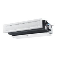
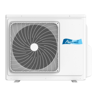
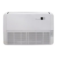
Visual representation and identification of indoor and outdoor units.
Highlights key capabilities and advantages of the air conditioning system.
Detailed description of the indoor unit's functionalities and design aspects.
Comprehensive technical data including capacity, dimensions, power, and noise levels.
Provides physical measurements and diagrams for the indoor unit.
Specifies clearance requirements for installation and maintenance of the indoor unit.
Illustrates electrical connections for the indoor unit and its components.
Presents cooling and heating capacity data under various operating conditions.
Details electrical specifications such as voltage, frequency, and motor power.
Shows a detailed breakdown of the indoor unit's parts for repair and maintenance.
Lists included installation fittings and optional components for the indoor unit.
Outlines power supply requirements and wiring specifications for the indoor unit.
Instructions for connecting the indoor and outdoor units with power and control wiring.
Lists common error codes and descriptions for indoor unit diagnostics.
Comprehensive technical data for outdoor units, including capacity, power, and dimensions.
Provides physical measurements and diagrams for the outdoor units.
Specifies clearance requirements for installation and maintenance of the outdoor unit.
Illustrates electrical connections for the outdoor unit and its components.
Details electrical specifications for the outdoor unit, including motor power.
Defines acceptable ranges for outdoor and room temperatures for operation.
Provides noise level measurements for the outdoor units.
Shows detailed breakdown of outdoor unit parts for repair and maintenance.
Lists error codes and definitions for outdoor unit diagnostics and fault finding.
Essential safety measures and guidelines before starting the installation process.
Procedures for dehydrating and leak testing the refrigerant system.
Instructions for adding refrigerant based on pipe length and diameter.
Guidelines for proper installation and configuration of the unit's drainage system.
Procedures and material specifications for insulating refrigerant and drainage pipes.
Steps to verify correct operation of the system after installation.
Detailed guide on operation, features, and installation of the wired remote controller.
| Cooling Capacity | 18000 BTU/h |
|---|---|
| Refrigerant | R32 |
| Energy Efficiency Ratio (EER) | 3.21 |
| Coefficient of Performance (COP) | 3.61 |
| Power Supply | 220-240V, 50Hz |
| Indoor Unit Noise Level | 42 dB(A) |
| Indoor Unit Dimensions (WxHxD) | 970x300x224 mm |
| Type | Split System Air Conditioner |