15-4
OPTIONAL ACCESSORIES
SM FBFRPM 1-A.0 GB
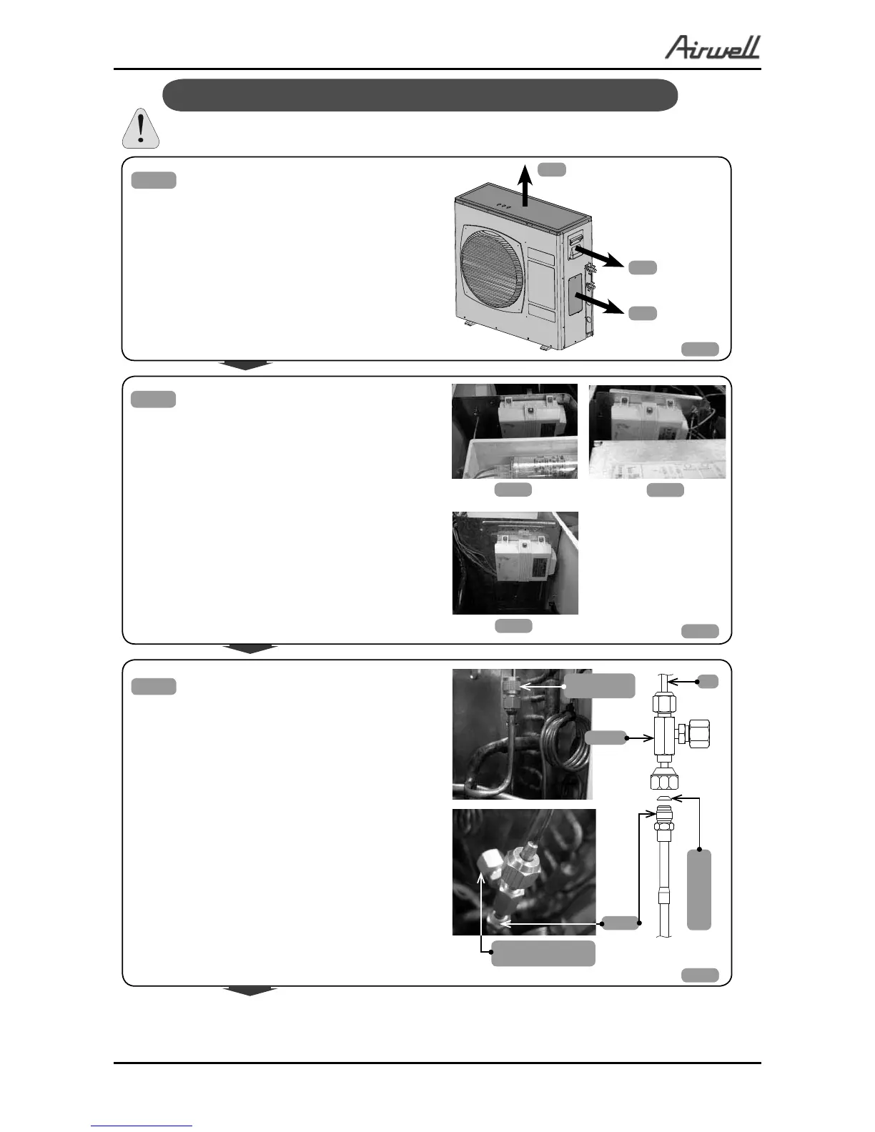
All Season Kit Installation Instruction(for ST units only)
Switch off power supply to the unit
Fig.1
Fig.2
● Mount the Fan speed controller on the partition
of the compressor compartment in the holes pro-
vided, using four supplied screws .
Note:
● In outdoor models OU8, the Fan Speed Control-
ler should be mounted on the partition toward the
outdoor fan motor side.
OU7
OU8
OU10
Fig.3
● Unscrew the cap of the provided service valve D
and connect to the T-valve, supplied in the kit.
Use Copper sealing gasked between the flare nut
and it’s connection to service valve D.
Note:
● The “T-valve” supplied in the kit is installed be-
tween valve D and capillary E offering the possi-
bility of an additionall pressure connecting output
for service.
A
C
Additional pressure
output
E
T-valve
D
B
Service valve
cap
gn
i
l
a
es repo
o
C
t
eksag
● Remove:
– Cover A;
– Power panel handle B;
– Side cover C (if it exist).