11-35
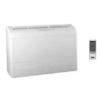
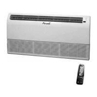
CONTROL SYSTEM
SM FBFRPM 1-A.0 GB
11.16 System Diagnostics
Pressing Mode button for 5-10 seconds in SB or any other operation mode will activate
the DIAGNOSTICS mode, acknowledged by 3 short beeps and lighting of COOL and
HEAT LEDs.
In DIAGNOSTICS mode, system failures will be indicated by the blinking of HEAT &
COOL LEDs.
The coding method is as follows:
x HEAT LED blinks 5 times in 5 seconds, and then turns off for the next 5
seconds.
x COOL LED blinks during the same 5 seconds according to the following table:
No. Problem 1 2 3 4 5
1 RT1 is disconnected żƔƔƔƔ
2 RT1 is shorted żƔƔƔż
3 RV fault żƔƔżƔ
4 RT2 is disconnected ƔżƔƔƔ
5 RT2 is shorted ƔżƔƔż
6 (Reserved) ƔżƔżƔ
7 RT2 temp reading doesn’t change ƔżƔżż
8 RT3 is disconnected ƔƔżƔƔ
9 RT3 is shorted ƔƔżƔż
10 (Reserved) ƔƔżżƔ
11 RT3 tem
p reading doesn’t change ƔƔżżż
12 RT2 & RT3 temp reading doesn’t change Ɣżżżż
LEGEND
ż - ON, Ɣ - OFF
NOTES
1. If faults occur in more than one thermistor (except case
number 12 in table above), only one fault will be indicated
according to the following order: RT3, RT2, RT1.
2. A/C will return to normal mode when sending a command by
the R/C during system DIAGNOSTICS mode. If the command
from the R/C contains a Group ID, the ID will become the new
Group ID of the ELCON unit.