11
6.2 Recommendation For Interconnection Tubing Installation
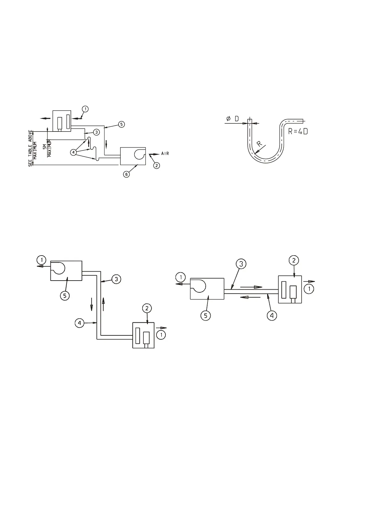
Three possible versions are schematically illustrated:
1) The outdoor unit installed above the indoor unit (Figure 9) - such installation requires an oil trap
in the suction line at the lowest point of the riser. The radius of the oil trap should be as short as
possible (See Figure 10). Horizontal runs of suction line should have a 0.5% minimum pitch
toward the outdoor unit. Liquid line should follow the suction line (except for trap). In case the
insulation must be partially removed for installation purposes, it is imperative that lines be fully
insulated with Armaflex, or equivalent insulation, after installation has been completed.
1. Air
2. Air
3. Suction Line
4. Oil trap every
3 m.
5. Liquid Line
6. Indoor unit
7. See Table
8. Outdoor Unit
Figure 9. Interconnecting Tubing - Outdoor Unit
above Indoor Unit
Figure 10. Tube Bending
2) The outdoor unit is installed below the indoor unit (Figure 11) - no trap is required in such
installation. Besides it, the same applies as above.
3) The units are installed at the same level (Figure 12) - no trap is required in such installation.
Besides it, the same applies as above.
1. Air
2. Outdoor Unit
3. Liquid Line
4. Suction Line
5. Indoor Unit
1. Air
2. Outdoor Unit
3. Suction Line
4. Liquid Line
5. Indoor Unit
Figure 11. Interconnecting Tubing - Outdoor Unit
Below Indoor Unit
Figure 12. Interconnecting Tubing - Outdoor Unit and
Indoor Unit at the Same Level
 Loading...