Do you have a question about the Airwell HDLA-025N-09M25 and is the answer not in the manual?
Essential warnings for safe operation, handling potential abnormal situations and misuse.
Crucial safety guidelines for electrical connections, wiring, and power supply to prevent hazards.
Key safety precautions and warnings for ensuring correct and safe installation of the unit.
Specific safety protocols and environmental considerations for refrigerants R32 and R290.
Regulations and methods for environmentally responsible disposal of electrical equipment in Europe.
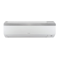
Overview of the indoor unit's display windows, indicators, and symbols.
Recommended temperature ranges for COOL, HEAT, and DRY modes for optimal performance.
Details on additional functions like Auto-Restart, Anti-mildew, Wireless Control, and Louver Memory.
Instructions for operating the unit using the manual button when the remote control is lost.
Step-by-step instructions for cleaning the interior parts of the indoor unit.
Guide on cleaning air filters to maintain cooling efficiency and air quality.
Procedures for preparing the unit for storage during extended periods of inactivity.
A list of common problems and their potential causes that do not necessarily indicate a malfunction.
Troubleshooting steps and potential causes for reduced cooling efficiency in the unit.
Solutions and checks for when the air conditioning unit fails to start or operate.
Essential checks and information before beginning the indoor unit installation process.
Guidelines for choosing an appropriate and safe location for the indoor unit.
Instructions for securely installing the mounting plate for the indoor unit.
Procedures for drilling the wall hole required for refrigerant and drain piping.
Steps for preparing the refrigerant piping before connecting it to the unit.
Detailed instructions for connecting the drain hose to ensure proper water drainage.
Guidance on properly connecting signal and power cables to the indoor unit's terminals.
Instructions for bundling and insulating refrigerant pipes, drain hose, and signal cable for protection.
Steps for securely mounting the indoor unit onto the wall bracket.
Criteria and considerations for selecting the optimal location for the outdoor unit.
Instructions for installing the drain joint on the outdoor unit for heat pump models.
Procedures for securely anchoring the outdoor unit to a mounting platform or bracket.
Guidance on connecting signal and power cables to the outdoor unit's terminal block.
Information on the impact of refrigerant pipe length on unit performance and energy efficiency.
General guidance and precautions for connecting refrigerant pipes.
Steps for removing burrs from pipe ends to ensure an airtight seal.
Instructions for properly flaring pipe ends to achieve secure and leak-free connections.
Procedures for connecting the refrigerant pipes to the indoor and outdoor unit valves.
Essential preparatory steps and safety warnings before conducting air evacuation.
Detailed procedure for evacuating non-condensable gases and moisture from the refrigerant circuit.
Guidelines for calculating and adding refrigerant based on pipe length and system requirements.
Mandatory checks to perform on electrical safety and gas connections before the unit test run.
Verification of electrical system integrity, grounding, and terminal connections.
Methods for detecting refrigerant leaks at all pipe connection points.
Procedures and checks to confirm proper unit operation after installation and checks.
Re-verification of refrigerant pipe connections during the test run to ensure no leaks.
| Model | HDLA-025N-09M25 |
|---|---|
| Brand | Airwell |
| Category | Air Conditioner |
| Type | Split System |
| Cooling Capacity | 2.5 kW |
| Heating Capacity | 2.8 kW |
| Energy Efficiency Ratio (EER) | 3.33 |
| Refrigerant | R410A |
| Outdoor Unit Noise Level | 52 dB(A) |
| Air Flow (Indoor) | 500 m³/h |
| Cooling Capacity (W) | 2500 W |
| Cooling Power Input | 750 W |
| Power Supply | 220-240V/50Hz |
| Operating Temperature (Cooling) | -10°C to 46°C |