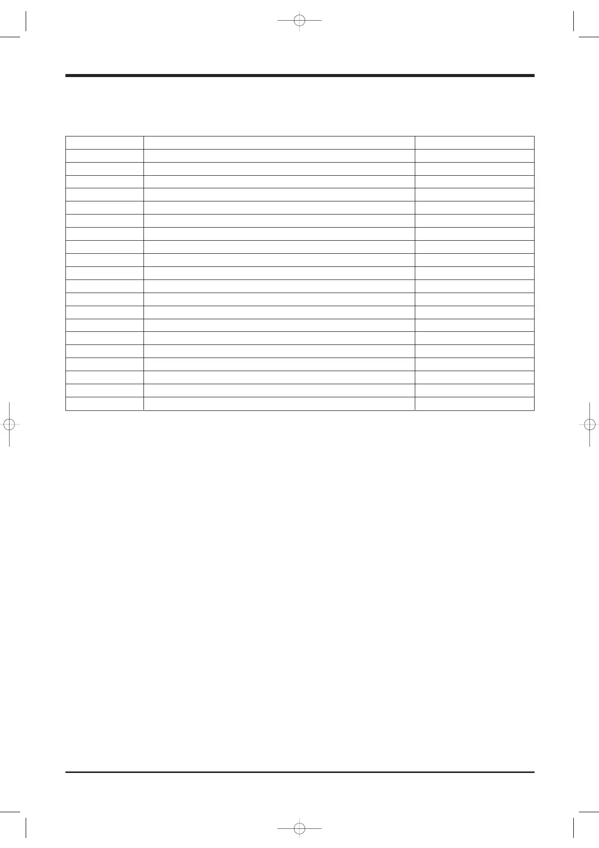
EasyManua.ls Logo

Airwell Itelco-Clima CLS 402 STD User Manual

Airwell Itelco-Clima CLS 402 STD
83 pages
To Next Page IconTo Next Page
To Previous Page IconTo Previous Page
Page #25 background imageLoading...
Page #25 background image
Page 24
Control
6.6 Main alarms
Once you have solved the problem that originated
the alarm, reset the alarms by pressing the ON-OFF
button.
E00 does not close the relay that signals an alarm
state (terminals 121-122)
High pressure alarm
When this alarm is activated, the control system halts
the operation of the involved refrigeration circuit and
opens the compressor’s control chain (safety against
failures). The alarm is reset manually from the control
panel when the pressure switch has been reset auto-
matically.
Low pressure alarm
When this alarm is activated, the control system halts
the operation of the involved refrigeration circuit.
The activation of this alarm is inhibited for approx.
40 seconds from start-up. The reset is automatic for
the first three times during the same hour. Upon the
fourth activation, a manual reset is required.
Antifreeze alarm
This alarm is enabled when the temperature of the
fluid leaving the evaporator drops below 4 °C. After
the activation of this alarm, the control system halts
the operation of the involved refrigeration circuit.
The reset is manual from he control panel.
External interlock alarm
When this alarm is activated, the control system halts
the operation of the unit. The reset is automatic.
Code Description Reset
E00 Remote Off Automatic
E01 High pressure 1 Manual
E02 Low pressure 1 Automatic/manual
E03 Thermal protection, compressor 1 Manual
E04 Thermal protection, fans Manual
E05 Antifreeze, circuit 1 Manual
E06 Failure of leaving water sensor 1 Automatic
E07 Failure of coil sensor 1 Automatic
E21 High pressure 2 Manual
E22 Low pressure 2 Automatic/manual
E23 Thermal protection, compressor 2 Manual
E25 Antifreeze, circuit 2 Manual
E26 Failure of leaving water sensor 2 Automatic
E27 Failure of coil sensor 2 Automatic
E40 Failure of entering water sensor Automatic
E41 Flow meter - no water Manual
E42 Failure of ST4 sensor Automatic
E44 Machine discharge Manual
E45 Configuration error Manual
E46 High temperature of entering water Automatic
Manuale CLS-CLH1 7.2.2005 10:17 Pagina 24

Table of Contents

Questions and Answers:

Airwell Itelco-Clima CLS 402 STD Specifications

General IconGeneral
BrandAirwell
ModelItelco-Clima CLS 402 STD
CategoryChiller
LanguageEnglish

Summary

1 FOREWORD

1.1 Introduction

General introduction to Itelco-Clima units and the manual.

1.2 Warranty

Details warranty conditions and exclusions for the unit.

1.3 Emergency Stop and Normal Stop

Explains how to perform emergency and normal stops on the unit.

1.4 Introduction to the Manual

Explains manual conventions and safety information.

2 SAFETY

2.1 Foreword

General safety compliance and installation requirements.

2.2 Definitions

Defines roles like OWNER and INSTALLER.

2.3 Access to the Unit

Specifies access requirements and safety for personnel.

2.4 General Precautions

Lists precautions for operators and installers.

2.5 Precautions Against Residual Risks

Details risks related to control, mechanical, and electrical systems.

2.6 Precautions During Maintenance Operations

Outlines safety measures before and during maintenance.

2.7 Safety Plates

Describes identification labels affixed to the unit.

2.8 Safety Regulations

Details safety data for refrigerants and oils.

3 TRANSPORT, LIFTING AND POSITIONING

3.1 Inspection

Instructions for checking the unit upon delivery.

3.2 Lifting

Guidelines and precautions for safely lifting the unit.

3.3 Anchoring

Notes on securing the unit to foundations.

3.4 Storage

Precautions for storing the unit before installation.

4 INSTALLATION

4.1 Positioning of the Unit

Guidelines for selecting the unit's installation location.

4.2 Installation of Spring Shock Absorbers

Procedure for installing optional vibration-reducing supports.

4.3 External Hydraulic Circuit

Requirements for the external hydraulic system.

4.4 Hydraulic Connection

Details on connecting the unit's water fittings.

4.5 Draining the Defrosting Waste Water

Instructions for heat pump units regarding defrost water.

4.6 Power Supply

Safety precautions for electrical connections.

4.7 Electrical Connections

Detailed requirements for electrical hook-up.

5 START-UP

5.1 Preliminary Check

Essential checks before unit start-up.

5.2 Start-up

Step-by-step procedure for initial unit operation.

5.3 Checking the Operation

Key parameters to check during unit operation.

5.4 Delivery to the Customer

Instructions for user training upon delivery.

6 CONTROL

6.1 General Information

Overview of the unit's control and monitoring system.

6.2 Control System

Details on temperature regulation and antifreeze functions.

6.3 Display

Explanation of the control panel display and LED indicators.

6.4 Start-up

Procedure for starting different unit models.

6.5 Switching the Working Temperature

How to change operating modes (cooling/heating).

6.6 Main Alarms

List and description of common unit alarms.

7 GENERAL DESCRIPTION

7.1 Introduction

Introduction to CLS/CLH units and their applications.

7.2 General Specifications

Details on unit construction, materials, and testing.

7.3 Compressors

Information on the hermetic scroll compressors used.

7.4 Refrigeration Circuits

Description of the unit's dual refrigeration circuits.

7.5 Water Heat Exchanger

Details on the stainless steel plate type evaporators.

7.6 Air Heat Exchanger

Description of the copper coil and aluminium finned pack.

7.7 Fans

Information on axial type condenser fans.

7.8 Electric Power Supply and Control System

Description of the control compartment and its components.

7.9 Accessories

List of optional accessories available for installation.

8 TECHNICAL DATA

8.1 Pressure Drops in the Evaporator

Table showing pressure drop values for various models.

8.2 Technical Data

Comprehensive technical specifications covering various CLS/CLC/CLH model series and configurations.

8.3 Unit Electrical Data

Electrical specifications including voltage, power, current, and cable sizing.

8.4 Position of Shock Absorbers and Weight Distribution on Supports

Support positions and weight distribution for basic and pumped units.

8.5 Overall Dimensions

Dimensional drawings and measurements for various unit models.

8.6 Service Spaces

Required clearance for installation and service of single and multiple units.

9 MAINTENANCE

9.1 General Requirements

General requirements for unit maintenance.

9.2 Planned Maintenance

Scheduled maintenance tasks and frequency.

9.3 Refrigerant Charge

Procedures and precautions for refrigerant charging.

9.4 Compressor

Information on compressor maintenance and replacement.

9.5 Condenser

Guidelines for cleaning and maintaining the condenser coils.

9.6 Fans

Instructions for checking fan rotation and maintenance.

9.7 Dehydrating Filter

Maintenance and checks for the dehydrating filter.

9.8 Sight Glass

Using the sight glass for refrigerant flow and humidity checks.

9.9 Thermostatic Expansion Valve

Procedure for checking and adjusting overheating.

9.10 Evaporator

Maintenance advice for the evaporator heat exchanger.

10 TROUBLESHOOTING

11 SPARE PARTS

11.1 Spare Part List

List of recommended spare parts for initial operation.

11.2 Oil for Compressors

Information on the type of oil used in compressors.

11.3 Wiring Diagrams

Location and request procedure for wiring diagrams.

12 DISMANTLING, DEMOLITION AND SCRAPPING

12.1 Generalities

General procedures for unit disassembly and disposal.

Related product manuals