Page 26
General Description
7.5 Water heat exchanger
The evaporators are of stainless steel plate type.
Their thermal insulation is ensured by a thick flexible
closed-cell heat-insulating jacket.
Furthermore, the frost protection is ensured by elec-
tric heaters. These exchangers can work at pressures
up to 10 bar on the hydraulic side and 30 bar on the
refrigerant side.
The hydraulic connections to the evaporator are of
2” Victaulic type, while the connection to the net-
work is ensured by 2” threaded male fittings.
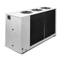
7.6 Air heat exchanger
Coils are made of copper pipes in staggered rows,
mechanically expanded inside an aluminium finned
pack.
7.7 Fans
Fans are of directly coupling propeller type, provid-
ed with aluminium blade with wing profile.
Each fan is provided with galvanised steel accident-
prevention guard.
Finally, motors are completely closed, protection
class IP54, protection thermostat immersed in wind-
ings.
The continuous speed regulator is provided as shop-
mounted accessory (standard on the ELN version).
Components of the hydraulic plant
(optional):
A Shut-off valve
B Pump(s)
C Nonreturn valve
D Expansion valve
E Plant discharge safety valve
F Air vent
G Filling valve
H Discharge valve
I Pressure gauge
L Storage tank
Components of the refrigeration
system:
1 Compressors C1 / C2
2 Delivery cock
3 Silencer (ELN only)
4 Coil
5 PED safety valve
6 Liquid cock
7 Filter
8 Liquid sight glass
9 Thermostatic valve
10 Plate-type heat exchanger
Safety devices:
A HP pressure switch
B LP pressure switch
C Transducer
D Water differential pressure switch
Pressure and charge/discharge inlets
Freon
CLS refrigeration diagram
REFRIGERATION PLANT
HYDRAULIC PLANT (OPTIONAL)
 Loading...