Do you have a question about the Airwell PNX 012 and is the answer not in the manual?
| Brand | Airwell |
|---|---|
| Model | PNX 012 |
| Category | Air Conditioner |
| Language | English |
Covers system overview, key features, and tubing connection details.
Details on inbox documentation, matching tables, and unit combinations.
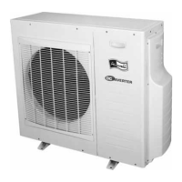
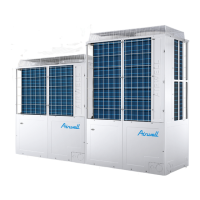
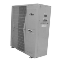
Detailed specifications for the Cinco 100 DCI outdoor unit.
Cooling and heating capacity data for various Cinco DCI configurations.
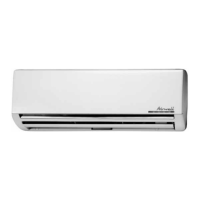
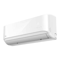
Technical specifications for various types of indoor units.
Defines the operational limits for indoor and outdoor units in cooling and heating.
Dimensional drawings and mounting template for PNX009 and PNX012 indoor units.
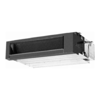
Dimensional drawings for HFD007 and HFD009 indoor units.
Dimensional drawings for HFD012 indoor unit.
Dimensional drawings for HFD018 indoor unit.
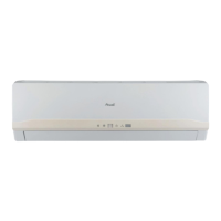
Dimensional drawings for HAD007 and HAD009 indoor units.
Dimensional drawings for HAD012 indoor units.
Dimensional drawings for HAD018, HAD021, and HAD024 indoor units.
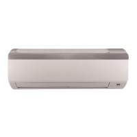
Dimensional drawings for XLF009 and XLF012 indoor units.
Dimensional drawings and table for CK series indoor units.
Dimensional drawings for SX series indoor units.
Dimensional drawings and capacity table for DLF series indoor units.
Dimensional drawings and parts table for DLS series indoor units.
Dimensional drawings for the Cinco 100 DCI outdoor unit.
Cooling and heating performance data for Delta and LEX indoor units.
Cooling capacity factors for LEX 25 DCI units based on temperature conditions.
Cooling capacity factors for LEX 35 DCI units based on temperature conditions.
Cooling capacity factors for LEX 50 DCI units based on temperature conditions.
Cooling capacity factors for LEX 60 DCI units based on temperature conditions.
Cooling capacity factors for LEX 70 DCI units based on temperature conditions.
Cooling capacity factors for CN 25 DCI units based on temperature conditions.
Cooling capacity factors for CN 35 DCI units based on temperature conditions.
Cooling capacity factors for CN 50 DCI units based on temperature conditions.
Cooling capacity factors for CN 60 DCI units based on temperature conditions.
Cooling capacity factors for CN 70 DCI units based on temperature conditions.
Cooling capacity factors for PXD 25 DCI units based on temperature conditions.
Cooling capacity factors for PXD 35 DCI units based on temperature conditions.
Cooling capacity factors for PXD 50 DCI units based on temperature conditions.
Cooling capacity factors for PXD 60 DCI units based on temperature conditions.
Cooling capacity factors for PXD 70 DCI units based on temperature conditions.
Graphs showing capacity correction factors for tubing length in cooling and heating.
Table of model correction factors for capacity and power input.
Suction and discharge pressure curves for cooling operation.
Suction and discharge pressure curves for heating operation.
Graphs showing pressure ratio correction factors for tubing length.
Table of correction factors based on outdoor unit code.
Example calculation for cooling pressure adjustment.
Information regarding outdoor unit sound level measurements.
Sound pressure level spectrum graphs for cooling and heating.
Electrical specifications for the Cinco 100 DCI, including power supply and wiring.
Wiring diagram for the Cinco 100 DCI outdoor unit.
Diagram showing power supply connections to the outdoor unit.
Refrigerant system diagram for the Cinco 100 DCI outdoor unit.
Table of torque specifications for various tubing connections and components.
Glossary of abbreviations used in the control system section.
General overview of the control system, including block diagrams and controller details.
Covers communication, system configuration, and temperature measurements.
Explains load calculation, fan control modes, and operational sequences.
General definition, control functions, and sequence diagrams for dry mode.
General definition, control functions, and sequence diagrams for sleep mode.
Procedure for setting and operating the unit in forced mode.
Explains operations when indoor unit modes differ from outdoor unit and other controls.
Details on unit controls and indicators for different models.
Defines the default operation mode and how systems transition between modes.
Rules and procedures for controlling the Electronic Expansion Valve (EEV).
General rules and behavior for outdoor fan speed control.
Defines protection levels and lists IDU and ODU protections.
Procedures for testing installation, identifying faults, and correcting issues.
Procedure for entering, operating, and exiting technician test mode.
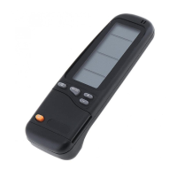
Describes the remote control's user interface, keys, and menu structure.
Configuration settings using jumpers and DIP switches for IDU and ODU.
Lists system parameters, ODU dependent parameters, and indoor unit SW parameters.
Important warnings regarding high voltage, charged capacitors, and handling electrical components.
Common system failures for indoor and outdoor units with troubleshooting steps.
Guides to diagnose and resolve faults using outdoor and indoor unit codes.
Step-by-step guides for checking electrical components like drivers, motors, and sensors.
Detailed instructions for safely removing and replacing major unit components.
Exploded views and a comprehensive list of spare parts for the outdoor unit.
Information on RCW and RCW2 wall-mounted remote controls for system management.
Installation instructions for base heater, crank case heater, and room thermostat.
Details on transitions for connecting different pipe diameters.
Reference to the specific installation manual for the Cinco 100 DCI.