M
Megan MooreAug 14, 2025
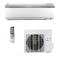
What causes communication malfunction in Airwell AWSI-HZDE009-H11?
- YyoungdeanAug 14, 2025
The E6 error code on your Airwell Air Conditioner signifies a communication malfunction. This could be due to wiring mistakes or a problem with the IDU (Indoor Unit) or ODU (Outdoor Unit) PCB (Printed Circuit Board).