EasyManua.ls Logo

Airwell AWSI-HHF009-H11 User Manual

Airwell AWSI-HHF009-H11
69 pages
To Next Page IconTo Next Page
Page #1 background imageLoading...
Page #1 background image
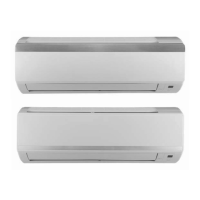
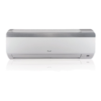
HGF / HHF Series
Indoor Units Outdoor Units
AWSI-HGF009-H11 AWSI-HHF009-H11 AWAU-YGF009-H11
AWSI-HGF012-H11 AWSI-HHF012-H11 AWAU-YGF012-H11
AWSI-HGF018-H11 AWSI-HHF018-H11 AWAU-YGF018-H11
AWSI-HGF024-H11 AWSI-HHF024-H11 AWAU-YGF024-H11
REFRIGERANT
R410A HEAT PUMP
SM HGFHHF 1-A.1 GB
March- 2011
Version:2

Questions and Answers:

Airwell AWSI-HHF009-H11 Specifications

General IconGeneral
BrandAirwell
ModelAWSI-HHF009-H11
CategoryAir Conditioner
LanguageEnglish

Summary

Introduction to Airwell HGF/HHF Series

General Unit Information

Overview of the HGF/HHF/YGF series air conditioners and their models.

Key Features of the Air Conditioner

Highlights the key technological innovations and benefits of the air conditioning units.

Indoor Unit Description

Details the features and design of the wall-mounted indoor unit.

Outdoor Unit Description

Describes the installation, features, and components of the outdoor units.

Product Data Sheets for Airwell Units

HGF009/HHF009 // YGF009 Specifications

Detailed technical data for the HGF009/HHF009 indoor and YGF009 outdoor units.

HGF012/HHF012 // YGF012 Specifications

Detailed technical data for the HGF012/HHF012 indoor and YGF012 outdoor units.

HGF018/HHF018 // YGF018 Specifications

Detailed technical data for the HGF018/HHF018 indoor and YGF018 outdoor units.

HGF024/HHF024 // YGF024 Specifications

Detailed technical data for the HGF024/HHF024 indoor and YGF024 outdoor units.

Rating Conditions and Operating Limits

Performance Data and Pressure Curves

Electrical Data for Airwell Units

Wiring Diagrams

Refrigeration Diagrams

Control System Operations

Electronic Control Overview

Details electronic control, abbreviations, operation concepts, and fan controls.

Operating Modes and Logic

Explains fan, cool, heat, auto, and dry modes, including operational logic.

Louver, Protections, and Indicators

Covers louver control, system protections, and indoor unit indicators.

Troubleshooting Airwell Units

Electrical & Control Troubleshooting Precautions

Safety precautions and initial checks for electrical and control system issues.

Diagnostics and Component Checks

Procedures for diagnosing unit faults and checking main components like motors and compressors.

Exploded Views and Spare Part Lists

Indoor Unit Exploded Views

Exploded view diagrams for indoor units HGF009/HHF009.

Indoor Unit Exploded View: HGF012/HHF012

Exploded view diagram for HGF012 and HHF012 indoor units.

Indoor Unit Exploded View: HGF018

Exploded view diagram for the HGF018 indoor unit.

Related product manuals