Do you have a question about the Airwell RC4 and is the answer not in the manual?
| Device Type | Remote Control |
|---|---|
| Brand | Airwell |
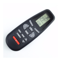
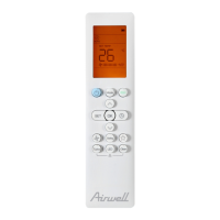
| Model | RC4 |
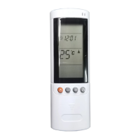
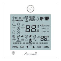
| Display | LCD |
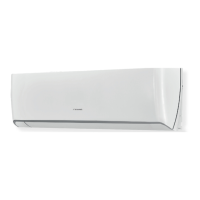
| Compatibility | Airwell Air Conditioners |
| Functions | Temperature control, Fan speed, Mode selection, Timer |
| Power Source | 2 x AAA batteries |
Procedures for receiving and handling the air conditioning unit safely, including transit damage checks.
Guidelines for selecting an appropriate and safe location for unit installation, considering drainage and noise.
Proper installation of condensate drainage for indoor and ducted units, ensuring slope and traps.
Duct design, fresh air intake considerations, and air filter requirements for ducted systems.
Guidelines for installing refrigerant lines, including pipe sizing, insulation, and leak testing procedures.
Procedures for evacuating the refrigerant system to remove moisture and charging it correctly.
Electrical installation must comply with regulations, wiring diagrams, and ensure adequate voltage.
Advice on selecting and operating units for efficient performance within specified conditions.
Details on the product warranty, conditions, and exclusions.
Using graphs to determine appropriate cable sizes for single and three-phase units.
Table showing cable ampacity based on size, installation method, and load.
Wiring diagram for single-phase systems, showing indoor and outdoor unit connections.
Wiring for single-phase systems, specifically for outdoor units under 7kW.
Wiring diagram for three-phase systems, showing indoor and outdoor unit connections.
Wiring for dual and quad systems in single-phase configurations.
Specifics for ducted, cassette, and console models, including pipe and cable sizes.
Specifics for hi-wall, inverter, duo, and multi-flow units, including pipe and cable sizes.
Essential checks before starting and verifying unit operation, covering electrical and visual aspects.
Verifying connections, final checks, and guidance for the customer on unit operation.
Procedures for accessing internal components and cleaning air filters.
Maintenance for fans, coils, electrical components, and the sealed refrigeration system.
A checklist for routine maintenance tasks to ensure optimum performance.
Details on operation modes, fan speed, temperature adjustment, and timers.
How to control airflow, louvres, and monitor room temperature.
Functions of various operating modes for temperature and humidity control.
Features for personalized temperature, scheduled operation, and comfortable sleep.
Managing humidity readings, auto louvre, and manual air direction.
Displaying room temperature, locking settings, and keypad illumination.
How DIP switches control modes and how to reset the remote controller.
Meaning of Standby, Operation, Timer, and Filter indicator lights on the unit.
Function of the Mode (Cool/Heat) and Filter reset/stop buttons on the unit.
Using buttons for manual operation and remote control via CLK terminals.
Procedure to start self-diagnosis and understand LED flash fault codes.
Detailed table of thermistor resistance (Ω) across a temperature range.
Table of DC voltage across temperature ranges for different unit types.
Steps to set the remote and unit for self-test, including LED and relay tests.
Testing thermistors, level switches, clock terminals, and CPU rise time.
List of part numbers and how the plug identifies unit types for the PCB.
Visual representation of loop connections for various unit types and their functions.
Unit behavior when outdoor coil temperature is high during cooling.
Unit behavior when indoor coil temperature is high during heating.
Unit response to low indoor coil temperatures and anti-freeze protection.
Details on static/dynamic initiation and time/temperature termination for de-icing.
Details on receiver units, optional expansion, and master controller setup.
Explanation of fault LEDs and important notes regarding softstarter installation.