VII. INSTALLING THE OPTIONAL HEATER ACCESSORY
NOTE
The optional Heater Accessory is intended to take
the chill out of the indoor air when the air is a few
degrees too cool for comfort. The Heater
Accessory is an effective “chill chaser”. It is not
a substitute for a furnace.
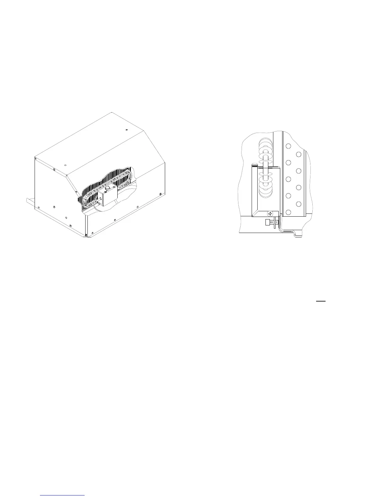
If the heater option is being installed, position the
heater assembly in the air conditioner return air
opening as shown in Figure 5. The heater bracket
must be installed over the metal basepan extrusion
and positioned between the basepan and the plastic
drain pan (See Figure 6). Tighten set screw to
secure the assembly so as to prevent movement.
Replace the selector switch control knob on the
ceiling assembly with that provided with the
optional heater.
FIGURE 5 FIGURE 6
VIII. INSTALLING THE CEILING ASSEMBLY (9300 SERIES)
Make sure that you have properly matched the roof top air
c
onditioner and interior ceiling assembly. The following step
by step instructions must be performed in the following
sequence to insure proper installation.
A. Carefully uncarton the ceiling assembly. Controls
are factory installed in the ceiling assembly (except
ceiling assemblies for applications with remote
control box/thermostat).
B. Remove the grille and filters from the ceiling
assembly.
C. STEP “C” CAN BE SKIPPED IF THE OPTIONAL
9233(X)4551 HEATER ACCESSORY PACKAGE
IS NOT INSTALLED AT THIS TIME.
Plug the heater cord into the 2 position receptacle
(See Figure 7).
TIE ALL WIRING TO INSURE NO CONTACT
WITH THE HEATER OR ANY SHARP EDGES.
KEEP IN MIND THAT HIGH VELOCITY AIR
WILL BE ENCOUNTERED IN THIS AREA.
D. Fasten the duct collar to the basepan of the air
conditioner with three (3) screws (See Figure 9).
E. Plug the roof top air conditioner electrical conduit
into the 9 position receptacle located in the
thermostat side of the ceiling assembly (See Figure 7).
F. Insert the supply wiring through the cable clamp and
into the field wiring box so that 4 - 6” of supply
conductor is inside the box. Secure the cable clamp
over the supply wire sheath so that no movement is
possible (See Figure 8).
G. Connect the supply power conductors to the black
and white pigtail wires and the supply ground wire to
the green pigtail wire found in the field wiring box
using the 3 provided wire nuts. IMPORTANT –
Connect the black supply to the black pigtail and the
 Loading...