8
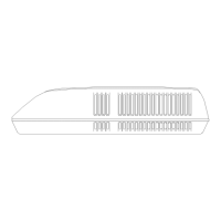
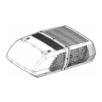
VI. FREE DELIVERY CEILING ASSEMBLIES
Selector Switch – Free Delivery Ceiling Assemblies
The selector switch is mounted on the left side of the
interior ceiling assembly. The selector switch allows the
unit to be operated on high to low blower only, or high to
low blower with compressor operation for cooling. On
heating and cooling models, the selector switch can also
switch in the electric heater at low blower operation only.
To check the selector switch, remove wires from the
terminals and rotate the switch to the proper position and
read continuity as follows:
Terminals Switch Position
L-1-3 Lo Heat
L-1 Lo Fan
L-2 Hi Fan
L-1-4 Lo Cool
L-2-4 Hi Cool
*If you do not wish to remove the wires from each
terminal, disconnect the 9 pin plug from the air
conditioning unit.
Thermostat (Mechanical Rotary)
The thermostat (temperature controller) is mounted on the
right side of the interior ceiling assembly. The thermostat
controls the on-off cycle of the compressor when the
selector switch is in the cooling position. On heating and
cooling models, the thermostat controls the on-off cycle of
the electric heater when the selector switch is in the
heating position. The thermostat is actuated by sensing the
temperature of the return air through the vent where the
bulb is located. Terminal continuity should make and
break if ambient air temperature is between 65 and 90
degrees F.
Heating Element
The heating element is a resistance heater of 1600 watts
(5600 BTUH) capacity and is connected across the line
when the selector switch is set for heating and the
thermostat is calling for heat. The current draw of the
heater (element only) will be 13.3 amperes at 120 volts
(domestic USA models).
Limit Switch
The limit switch is a safety switch and is mounted in the
heating element frame. It will open and break the circuit
on temperature rise in case the air flow through the heater
becomes low enough to cause the heater to overheat.
 Loading...