Do you have a question about the Aiwa AD-WX808 and is the answer not in the manual?
Details the power supply voltage and frequency.
Specifies frequency response for different tape types.
Details signal-to-noise ratio with NR systems.
Specifies wow and flutter for decks.
Schematic for the main circuit board.
Block diagram for IC LB1408.
Truth table for input control.
Continues the schematic for the main circuit board.
Schematic for SW-1 circuit board.
Schematic for SW-2 circuit board.
Schematic for the main circuit board.
Schematic for the Record/Playback/Erase head.
Schematic for Mechanism-1 circuit board.
Wiring diagram for the main circuit board.
Wiring diagram for SW-1 circuit board.
Wiring diagram for SW-2 circuit board.
Wiring diagram for Mechanism-1 circuit board.
Wiring diagram for Mechanism-2 circuit board.
Wiring diagram for TR circuit board.
Diagram of the power supply section.
Block diagram of the final amplifier.
Block diagram for IC LB1408.
Block diagram for IC 101 and IC 102.
Block diagram for IC 201 and IC 202.
Block diagram for IC 301 and IC 302.
Block diagram for IC 101 and IC 102.
Block diagram for IC 201 and IC 202.
Block diagram for IC 301 and IC 302.
Wiring diagram for Mechanism-1 circuit board.
Wiring diagram for Mechanism-2 circuit board.
Wiring diagram for TR circuit board.
Wiring diagram for Power circuit board.
Wiring diagram for FL circuit board.
Wiring diagram for SW-1 circuit board.
Wiring diagram for Power circuit board.
Block diagram for IC LB1408.
Block diagram for IC 6520H.
List of abbreviations used in block diagrams.
Procedures for adjusting the unit.
Block diagram for IC 101 and IC 102.
Block diagram for IC 201 and IC 202.
Adjusts normal speed using test tape.
Adjusts high speed using test tape.
Head adjustment procedure.
Adjusts head azimuth for optimal output.
Adjusts frequency response using test tape.
Adjusts playback sensitivity.
Adjusts bias OSC trap coil.
Adjusts record equalizer level.
Adjusts the peak meter display.
Pin description for IC LC6520H.
Specifies playback output levels.
Specifies PB/REC output levels.
Specifies PB/REC distortion limits.
Specifies playback noise levels.
Explains the dbx Noise Reduction System overview.
Describes operations in different modes (dbx ON/OFF).
Operation of the circuit when dbx is OFF.
Operation during dbx playback (decode mode).
Signal levels during decode mode.
Operation during dbx record (encode mode).
Explains functions of circuit sections.
Function of the RMS Level Sensor.
Function of RMS BPF and PRE-EMPHASIS.
Explains logic control operations.
Exploded view of PCB-A.
Exploded view of PCB-B.
Exploded view of PCB-C.
Exploded view of PCB-D.
Alteration parts list for Deck 1.
Alteration parts list for Deck 2.
List of accessories and package items.
Part details for Actuating Chassis PH Assy.
Part details for Head Housing PH Assy.
Part details for the belt.
Part details for Actuating Chassis PH Assy.
Part details for Head Housing PH Assy.
Part details for the belt.
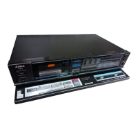
| Brand | Aiwa |
|---|---|
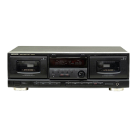
| Model | AD-WX808 |
| Track System | 4-track, 2-channel stereo |
| Tape Speed | 4.76 cm/s |
| Frequency Response (Metal tape) | 20 Hz - 20 kHz |
| Power Supply | AC 120V, 60Hz |
| Type | Dual Cassette Deck |
| Heads | 1 x Record/Playback, 1 x Erase |
| Motor | DC Motor |
| Inputs | Line In |
| Outputs | Line Out |
| Dimensions | 430 x 125 x 297mm |