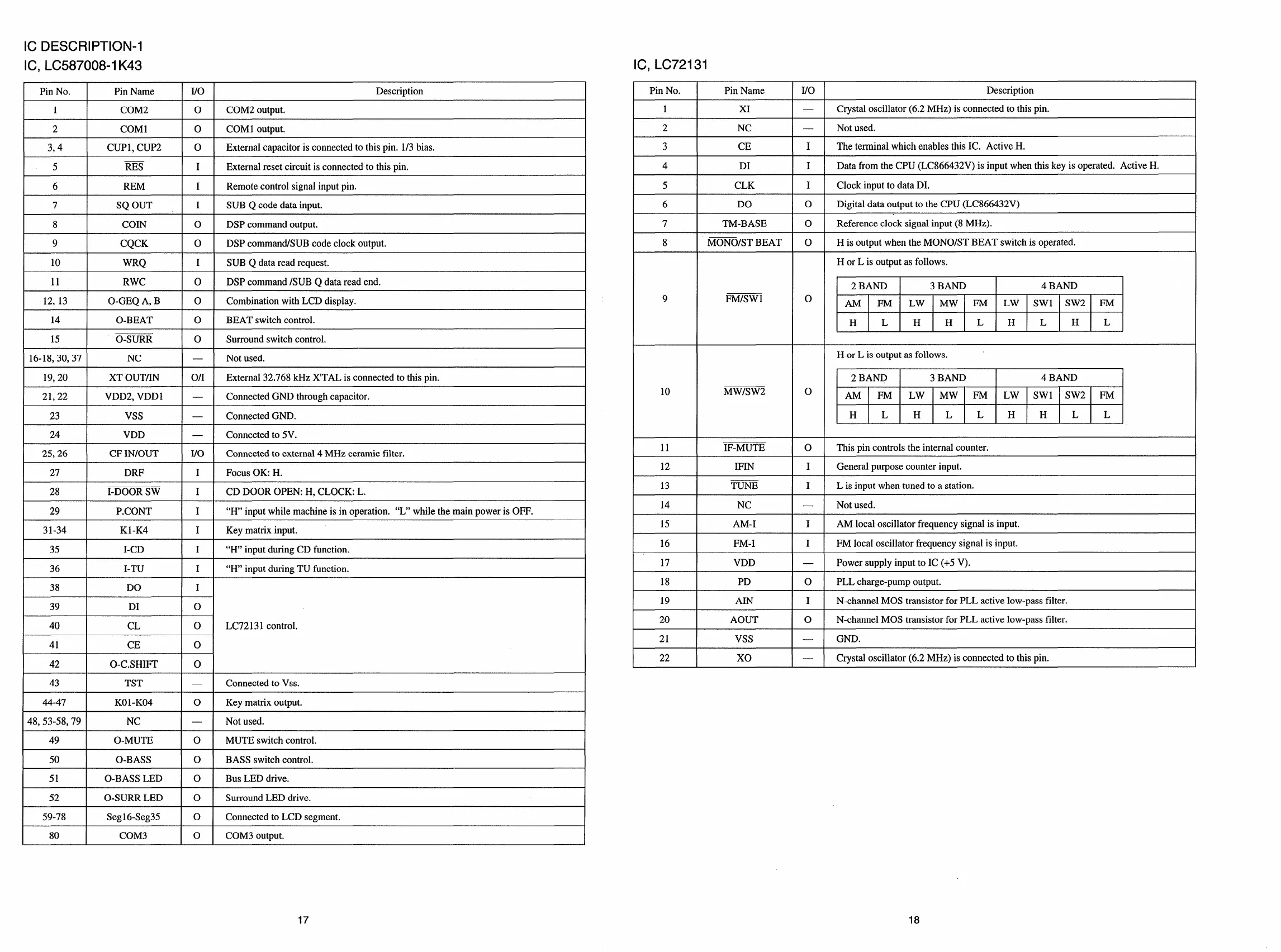
IC DESCRIPTION-I
IC, LC587008-I K43
IC, LC72131
Pin No.
Pin Name
I/o
Description
1
COM2
o COM2 output.
Pin No.
Pin Name
I/o
Description
1
2
XI
Crystal oscillator (6.2 MHz) is connected to this pin.
Not used.
—
—
2 COM1
o COM 1output.
3,4
CUP1, CUP2 o
External capacitor is connected to this pin. 1/3bias.
5 RES
I
External reset circuit is connected to this pin.
6 REM
I Remote control signal input pin.
7
SQ OUT
I SUB Q code data input,
8 COIN
o
DSP command output.
9
CQCK
o DSP command/SUB code clock output.
10
WRQ I SUB Q data read request.
NC
3 CE
I The terminal which enables this IC. Active H.
4 DI
I Data from the CPU (LC866432V) is input when this key is operated. Active H.
5 CLK
I
Clock input to data DI.
6
DO
o
Digital data output to the CPU (LC866432V)
Reference clock signal input (8 MHz).
His output when the MONO/ST BEAT switch is operated.
7 TM-BASE
o
MONO/ST BEAT8 0
H or L is output as follows.
2 BAND 3 BAND
4 BAND
AM FM
LW MW FM LW Swl SW2 FM
H L H H L H L H L
11 RWC
I
o
I
DSP command /SUB Q data read end.
9 FM/SW
o
0
12, 13
I
O-GEQ A, B
I
o
I
Combination with LCD display.
14
I
O-BEAT I O I BEAT switch control,
15
O-SURR o Surround switch control.
16-18,30,37 NC
—
Not used.
19,20
XT OUT/IN on External 32,768 kHz X’TAL is connected to this pin.
21,22
VDD2, VDD1 —
Connected GND through capacitor.
23
Vss
—
Connected GND.
24
VDD
—
Connected to 5V.
11
12
13
14
15
16
17
18
H or L is output as follows.
2 BAND 3 BAND
4 BAND
AM FM
LW MW FM
LW Swl SW2 FM
H L H L L H H L L
MWISW2
10
IF-MUTE
o
This pin controls the internal counter.
25,26 I CF IN/OUT I I/O I Connected to external 4 MHz ceramic filter.
IFIN I
General purpose counter input.
27 DRF
I
I Focus OK: H.
CD DOOR OPEN: H, CLOCK: L.
“H” input while machine is in operation. “L” while the main power is OFF.
Key matrix input.
“H” input during CD function.
“H” input during TU function.
TUNE
I
L is input when tuned to a station,
28
I-DOOR SW I
29 P.CONT I
31-34
K1-K4 I
35
I-CD I
36
I-TU
I
NC
Not used.
AM local oscillator frequency signal is input.
FM local oscillator frequency signal is input.
Power supply input to IC (+5 V).
PLL charge-pump output.
AM-I I
FM-I
VDD
PD
AIN
I
—
o
I
38
I
DO
I
I
l--
19
20
N-channel MOS transistor for PLL active low-pass filter.
39 DI
I
o
0
—
—
AOUT N-channel MOS transistor for PLL active low-pass filter.
40
CL
I
o LC72131 control,
I
21 Vss GND.
41
I
CE
I
22 Xo
Crystal oscillator (6.2 MHz) is connected to this pin.
42
O-C.SHIFI’
o
43
TST
—
44-47 KO1-K04 o
48,53-58,79 NC
—
49
O-MUTE o
Connected to Vss.
Key matrix output,
Not used.
MUTE switch control.
50 O-BASS
10
I
BASS switch control,
51 I O-BASS LED I O I Bus LED drive.
52
O-SURR LED o
Surround LED drive.
59-78 Seg16-Seg35 o Connected to LCD segment.
80 COM3 o COM3 output.
17
 Loading...