SERVICE MANUAL
TUNER
FM tuning range 87.5 MHz to 108 MHz
FM
AEP, UK models:
Except AEP, UK models:
usable sensitivity (IHF)
16.8 dBf
FM antenna terminal 75 ohms (unbalanced)
AM
AEP, UK, E, EA, TW models:
E51 model:
tuning range
531 kHz to 1602 kHz
AM usable sensitivity 350 µV/m
SP, AUS models:
530 kHz to 1710 kHz (10 kHz step)
531 kHz to 1602 kHz (9 kHz step)
AM antenna Loop antenna
AMPLIFIER
Power
AEP, UK models:
Except AEP, UK models:
output
Rated: 12 W + 12 W (6 ohms, T.H.D.
1 %, 1 kHz/DIN 45500)
Reference: 15 W + 15 W (6 ohms,
T.H.D. 10 %, 1 kHz/DIN 45324)
MUSIC POWER: 27 W +27 W
CASSETTE DECK
Track format 4 tracks, 2 channels stereo
Frequency response 50 Hz – 8 kHz
Recording system AC bias
Heads Deck A: playback x 1
Deck B: recording/playback x 1,
erase x 1
CD PLAYER
Laser Semiconductor laser
(λ = 780 nm)
Emission duration:
continuous
D/A converter 1 bit dual
Signal-to-noise ratio 85 dB (1 kHz, 0 dB)
Harmonic distortion 0.05 % (1 kHz, 0 dB)
AEP, UK models:
AEP, UK models:
Except AEP, UK models:
Power consumption
40 W
Power consumption With ECO mode on: 0.25 W
in standby mode With ECO mode off: 15 W
Dimensions (W x H x D) 280 x 330 x 392.5 mm
Weight
6.1 kg
Specifications and external appearance are subject to change
without notice.
13.2 dBf
530 kHz to 1710 kHz (10 kHz step)
531 kHz to 1710 kHz (9 kHz step)
Rated: 36 W + 36 W (1 kHz, T.H.D. 1
%, 6 ohms)
Reference: 45 W + 45 W (1 kHz,
T.H.D. 10 %, 6 ohms)
74 W
E, EA, SP, TW, AUS models: 6.8 kg
E51 model:
6.7 kg
Total harmonic distortion 0.08 % (6 W, 1 kHz, 6 ohms, DIN
AUDIO)
(Except AEP, UK models)
Input VIDEO/AUX: 400 mV
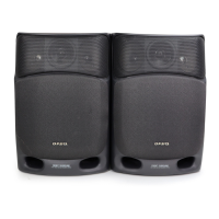
Outputs SPEAKER:
MIC: 1.7 mV (10k ohms)
6 ohms or more
PHONES: 32 ohms or more
COPYRIGHT
Check copyright laws relevant to recordings from discs, tuner
or tape for the country where the unit is to be used.
GENERAL
Power
AEP, UK models:
E, E51, SP models:
TW model:
requirements
230 V AC, 50/60 Hz
110
120 V AC, 50 Hz/60 Hz
- 120V / 220 - 240V AC
(Switchable), 50 Hz/60 Hz
EA model:
120 - 127V / 220 V AC
(Switchable), 50 Hz/60 Hz
AUS model:
240 V AC, 50 Hz/60 Hz
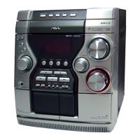
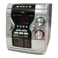
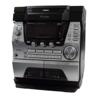
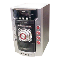
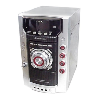
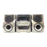
COMPACT DISC DECK RECEIVER
AEP Model
UK Model
E Model
Australian Model
CX-JN10
Ver 1.0 2004.03
9-877-593-01 Sony Corporation
2004C05-1 Home Audio Company
© 2004.03 Published by Sony Engineering Corporation
SPECIFICATIONS
CX-JN10 is the tuner, amplifier, cassette deck
and CD player section in JAX-N10/PK10.
Model Name Using Similar Mechanism CX-JN1
CD Mechanism Type CDM74S-K6BD72
CD
Base Unit Name BU-K6BD72
Section
Optical Pick-up Block Name KSM-213DCP
Optical Pick-up Name KSS-213D
Tape deck
Model Name Using Similar Mechanism CX-JN1
Section
Tape Transport Mechanism type CWM43FF13
• Abbreviation
AUS : Australian model
E51 : Chilean and Peruvian models
EA : Saudi Arabia model
SP : Singapore model
TW : Taiwan model