Do you have a question about the Aiwa XG-990 and is the answer not in the manual?
Detailed specifications for the FM tuner, including frequency range and sensitivity.
Specifications for the AM tuner, covering frequency range and sensitivity.
Specifications for Long Wave reception on specific models.
Details on the timer functions, including on-timer and sleep timer.
Power output and harmonic distortion specifications for the amplifier.
Specifications for the cassette deck, including frequency response.
Technical specifications for the CD player mechanism.
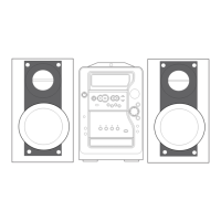
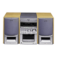
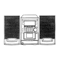
Specifications for the speaker system, including type and dimensions.
General specifications such as power requirements and overall dimensions.
Warning about hazardous radiation exposure from improper adjustments.
Warning regarding dangerous radiation exposure from non-specified procedures.
Procedure to adjust the tuner's clock frequency using TP1.
Procedure to check AM VT characteristics using TP2.
Procedure to check AM tracking sensitivity.
Procedure to adjust FM VT using TP2.
Procedure to adjust AM IF using TP6.
Procedure to adjust FM tracking using TP6.
Procedure to adjust DC balance using TP3 and TP4.
Procedure to adjust MPX VCO frequency using TP5.
Procedure to adjust the tuning LED lighting.
Procedure to adjust the vocal fader using SP OUT.
Procedure for adjusting DECK-2 normal playback speed.
Procedure for adjusting head azimuth on both decks.
Procedure for adjusting playback sensitivity on both decks.
Procedure to check playback frequency response.
Procedure to adjust REC/PB frequency response.
Procedure to adjust REC/PB sensitivity.
Procedure to adjust the CD VCO frequency using SFR4.
Procedure for adjusting focus bias when replacing optical block.
| Tuner | FM/AM |
|---|---|
| CD Player | Yes |
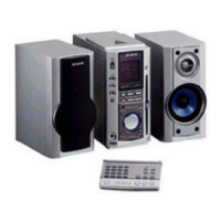
| Remote Control | Yes |
| Frequency Response | 20 Hz - 20 kHz |
| Total Harmonic Distortion | 0.5% |
| Speaker Impedance | 6 ohms |
| Power Requirements | AC 220-240V, 50/60Hz |
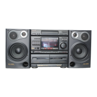
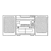
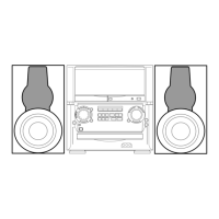
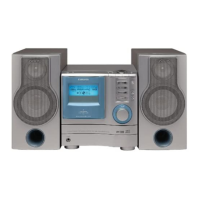
| Type | Stereo System |
| Speakers | 2-Way Bass Reflex |
| Cassette Deck | Double Cassette Deck |
| Signal to Noise Ratio | 80dB |