Do you have a question about the Aiwa XP-V420 and is the answer not in the manual?
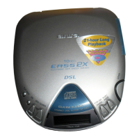
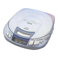
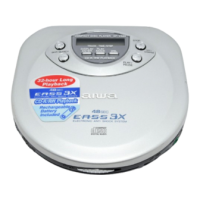
This document serves as a service manual for the AIWA SIMPLE-2 series of compact disc players, specifically covering models XP-V420 and XP-V421. It provides essential information for servicing, maintenance, and understanding the operational characteristics of these portable CD players.
The primary function of these devices is to play compact discs, offering a portable audio solution. They are designed for ease of use, allowing users to enjoy their music collection on the go. The players incorporate a basic CD mechanism, DA23LN, which is central to their disc reading capabilities.
The SIMPLE-2 series CD players are designed for straightforward operation. Users can insert a compact disc and initiate playback. The devices are equipped with standard controls for managing audio playback, such as play, pause, stop, and skip/search functions. These controls are typically intuitive, allowing for quick access to desired tracks or sections of a disc.
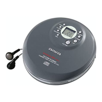
For audio output, the players feature a PHONES/LINE OUT jack, which is a stereo mini-jack. This allows for connection to headphones for private listening or to an external audio system for broader sound projection. The output is capable of delivering sufficient power for headphones and a line-level signal for other audio equipment.
Powering the device can be achieved through multiple options, enhancing its portability and versatility. Users can power the unit using two LR6 (size AA) alkaline batteries, providing a convenient cordless option for mobile use. Alternatively, two commercially available rechargeable batteries (Ni-Cd 1.2 V 700 mAh) can be used, offering an eco-friendly and cost-effective solution for repeated use. For stationary use, the players can be powered by an AC adaptor connected to a standard AC house current. The specific voltage and current requirements for the AC adaptor are provided to ensure compatibility and safe operation.
The physical design of the players emphasizes portability, with compact dimensions and a lightweight build, making them easy to carry in a bag or by hand. The external controls are positioned for accessibility, and the overall form factor is designed to be user-friendly.
The service manual provides critical information for maintaining and repairing the CD players, particularly focusing on the optical block, which is a key component for disc reading.
Protection of Eyes from Laser Beam During Servicing: A paramount safety instruction is provided regarding the laser beam. Since the device employs a laser, technicians are warned not to approach the laser exit too closely during servicing. If it's necessary to confirm laser beam emission, observation must be done from a distance of more than 30cm from the surface of the objective lens on the optical pick-up block. This warning is crucial to prevent hazardous radiation exposure. The device is classified as a CLASS 1 LASER product, and appropriate precautions must be taken when the casing is open and interlocks are defeated.
Precaution to Replace Optical Block (SF-P200): Replacing the optical block requires specific precautions due to the sensitivity of the laser diode to electrostatic discharge. Technicians are advised to ensure their body and workbench are grounded to prevent electrostatic potential from ruining the laser diode. Care must also be taken to ensure that clothing does not touch the diode during the replacement process. After the physical connection of the new optical block, a specific solder point, indicated in the manual, must be removed. This step is essential for the proper functioning and safety of the device after replacement.
Test Mode: The manual details a comprehensive test mode designed to facilitate adjustment-free servo circuit operation and disc distinction. This mode allows technicians to monitor and adjust various parameters, which are typically handled automatically by the IC during normal operation.
How to Start the Mode: The procedure for entering test mode varies depending on the type of disc being used (CD-DA, CD-R, or CD-RW). This is because the adjustment values for each servo differ based on disc type.
Disc Distinction (Confirmation of the FE Waveform): This mode allows for confirmation of the disc type. After selecting "CD-d" or "CD-r" using the DSL button, installing the disc, and pressing the MODE button, the LCD will display a judgment value and a measurement value in HEX. The judgment value helps understand which disc type the IC has selected, based on predefined ranges for "No disc," "CD-RW," and "CD-DA and CD-R." This also provides insight into the state of the FE waveform.
Confirmation of Sled Movement: By continuously pressing the F.SKIP or B.SKIP buttons in test mode, technicians can move the pick-up to the outer or inner side of the disc, allowing for inspection of the sled mechanism.
Confirmation of the RF Level: This involves checking the RF waveform at specific test points (RF and VC (Vref)) using a TCD-782 test disc. The manual provides an expected waveform pattern (0.8Vp-p or more) and oscilloscope settings (VOLT/DIV: 200mV, TIME/DIV: 0.5us) for accurate measurement.
Confirmation of Tracking Balance: The TE waveform can be confirmed at test points TE and VC (Vref) while playing a TCD-782 test disc and pressing the DSL button. The manual shows an expected TE waveform with A:B=1:1 and oscilloscope settings (VOLT/DIV: 200mV, TIME/DIV: 2ms).
Confirmation of Each Servo: This mode allows for confirmation of the adjustment value of each servo by repeatedly pressing the MODE button while a disc is playing. The switchover sequence for confirmation modes includes Focus Bias (FB), Tracking Balance (TB), Tracking Gain (TG), Tracking Error Offset (TEO), Focus Gain (FG), and Focus Error Offset (FEO). An example is provided showing how the LCD displays the Tracking Error Offset (TEO) and its adjustment value in HEX.
The manual also includes detailed electrical parts lists, transistor illustrations, FL (AHC-7) grid assignment/anode connection diagrams, wiring diagrams for both component and conductor sides of the main circuit board, schematic diagrams, IC block diagrams, IC descriptions with pin names and functions, and voltage charts for various ICs during CD play. These resources are invaluable for troubleshooting, component replacement, and ensuring the proper functioning of the CD player during service. Mechanical exploded views and parts lists are also included for physical assembly and component identification.
| Type | Portable CD Player |
|---|---|
| Battery Type | 2 x AA batteries |
| Frequency Response | 20Hz - 20kHz |
| Total Harmonic Distortion | 0.05% |
| Weight | 230g (without batteries) |
| Disc Capacity | 1 |
| Power Source | DC 4.5V (External Power Adapter) or Batteries |
| Outputs | Headphone Jack |
| Channels | Stereo |
| Dynamic Range | 85dB |
| Features | Repeat Play |