Do you have a question about the Aiwa Z-HT730 and is the answer not in the manual?
Details for FM reception tuning range, sensitivity, and antenna.
Details for MW reception tuning range, sensitivity, and antenna.
Details for LW reception tuning range, sensitivity, and antenna.
Power output, distortion, and input/output details.
Track format, frequency response, noise ratio, heads.
Laser, D-A converter, noise, distortion, wow/flutter.
Power requirements, consumption, dimensions, weight.
Cabinet type, speakers, impedance, SPL, dimensions, weight.
Cautionary advice regarding eye proximity to laser exit during servicing.
Steps to prevent damage to laser diode during replacement.
Procedure to safely discharge electrolytic capacitors before repair.
Verification steps before replacing the microcomputer.
Method to perform a forced reset on the microcomputer.
Checking solder joints of the microcomputer for faults.
Locations on the main PCB for tuning and deck adjustments.
Adjustment points on the MICON PCB for tuning.
Adjustment points on the Deck PCB for tape head alignment.
Verify clock signal frequency for tuner operation.
Check Voltage Tuning circuit performance for MW reception.
Adjust MW tracking for optimal signal reception.
Check Voltage Tuning circuit performance for LW reception.
Adjust LW tracking for optimal signal reception.
Adjust the Intermediate Frequency circuit for AM reception.
Check Voltage Tuning circuit performance for FM reception.
Verify FM tracking for optimal signal reception.
Adjust DC balance and mono distortion for audio quality.
Verify audio output levels for MW and FM modes.
Ensure proper stereo separation in FM reception.
Calibrate tape speed for accurate playback.
Align tape heads for optimal sound fidelity.
Verify playback frequency response accuracy.
Check playback sensitivity for tape signals.
Adjust recording and playback frequency response.
Verify recording and playback sensitivity.
Adjust the oscillator for the microcomputer control system.
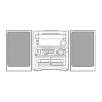
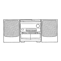
Instructions for disassembling speaker units (Type 1, 2, 3).
List of tools required for speaker disassembly.
Step-by-step guide to remove the front panel.
Instructions for reattaching the front panel.
| Brand | Aiwa |
|---|---|
| Model | Z-HT730 |
| Category | Stereo Receiver |
| Language | English |