After Sales Support
(AU) 1300 886 649 (NZ) 0800 836 761 | info@tempo.org
29
Installation (Cont.)
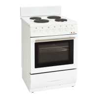
• The cooker should stand on a hard, even floor; do not put it on a base.
• Use the 2 expand screw to fix the saftey chain to the wall to prevent the
cooker tipping over (Fig. 13).
• Before you start using the cooker it should be
levelled, which is particularly important for fat
distribution in a frying pan. To this purpose,
adjustable feet are accessible after removal of
the drawer (Fig. 14). The adjustment range is
+/- 5mm.
• Take the cover and cooker out of the packaging. Select a proper place
and steadily level the cooker.
Fig. 13
INSTALLATION
7
Installing the cooker
l The kitchen should be dry and airy
a
nd have effective ventilation according
t
o the existing technical provisions.
l
The room should be equipped with a
ve
ntilation system that pipes away
e
xhaust fumes created during
c
ombustion.This system should consist
o
f a ventilation grid or hood.
Ho
ods should be installed according
t
o the manufacturer’s instructions.
Th
e cooker should be placed so as to
e
nsure free access to control
e
lements.
l
Coating or veneer used on fitted
f
urniture must be applied with a heat
r
esistant adhesive (100℃).This prevents
s
urface deformation or detachment of
t
he coating. If you are unsure of your
f
urniture’s heat resistance,you should
le
ave approximately 2 cm of free
a
pace around the cooker. The wall
b
ehind the cooker should be resistant
t
o high temperatures.During operation,
it
s back side can warm up to around
5
0℃ above the ambient temperature.
650mm(min)
2cm
2cm2cm
l The cooker should stand on a hard,
e
ven floor (do not put it on a base.)
l
Before you start using the cooker it
s
hould be leveled,which is particularly
im
portant for fat distribution in a frying
p
an. To this purpose,adjustable feet
a
re accessible after removal of the
d
rawer. The adjustment range is +/-5mm.
●
Take the cover and cooker out of the
p
ackaging.
S
elect a proper place,and steadily level
t
he cooker.
Installing the fixture bracket firstly by
s
crews provided, and stand cooker on
the slots preholed on the bracket to
p
revent its movement, see the
4
95mm
4
22mm
422
m m
l
illustration as below.
Drill a hole on the floor,and insert
l
l
column peg into the hole.See the
illu
stration
b
elow.as
8
To fit the rear panel/splashback, slide the lugs on the bottom of the
panel into the matching slots on rear of stove and fix with screws
p
rovided.
OPERATION
OPERATION
Remove the packaging from the internal cavities of the unit and empty the
b
ottom storage drawer.
Wip
e the interior of the oven with warm soapy water and wipe clean with a
lig
htly damp cloth or sponge.
Wip
e the cooktop in the same manner - but do not wipe down the solid
e
lements.
R
emove and wash the oven racks/trays with warm water and a little
d
ishwashing liquid.
En
sure plenty of ventilation is in the kitchen before proceeding - ensure
win
dows/doors are open and rangehood is turned on.
Th
e top surface of the hotplates are sealed with a heat resistant coating.
B
efore using for the first time, the hotplates should be heated for a short period
wit
hout a pan on it to harden the protective coating. If this is not done,
p
remature rusting may occur.
S
imply turn the heat setting to high for 3-4 minutes to fully harden the coating.
Wh
en the hotplates have cooled, apply a thin coating of "Shine On" to the
l
l
l
l
l
l
l
Before first use
 Loading...