EasyManuals Logo

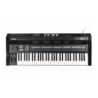
Akai AX80 Service Manual

Akai AX80
63 pages
To Next Page IconTo Next Page
To Previous Page IconTo Previous Page
Page #41 background imageLoading...
Page #41 background image
B
G
H
K
IC3
UPA80C
®
C3
0.01 (Z)
II
__
1j_
0
O
F
.-26.8V,;
J) a2®
^-26.8vP
^03®
^-28.0Vk
J>
a4®
^05®
^-
23.2
V,;
3
06®
^^2)
or®
^^08®
R
^^09®
^^0010®
^^01.®
^^0,2®
)b
®
IN
-2
5-263ZK
(AC)
i.
31.6V I
[
O
@H§h
V
-28.0V/J
^
al
®
c
26,8p
^
a2®
^-26.8V^
^
03®
C
28.0V^
^
a4®
^>
a5®
^-23.2V^
^
06®
C
2)
07®
^—
<l
5)
a8®
E
^-23.4V^
)
a9®
^<7)a,0®
^%o.l®
)
012®
)b
®
Voltages at
IC106
to
806 were
with
B-type
ICs,
voltages
with C-type
ICs will be
almost
the
same.
Voltages at
the
R0M(IC4 in
the
CPU
PCB) were with an
I-version,
voltages with
a K- version
ROM
will be
almost
the
same.
The unit was
in the P1
program
mode
with no key
function
(No function change
after
the
power
SW
was "ON"),
©with
voltage
indications
were
for
DC voltages
with
pulses,
voltages may vary
by
the
wave
forms.
Voltage indications
related
with
parameter
displays
No.
26,
28
and
32
of the
FLD
IN-2
in
FLD(
2)
PCB may vary with a
K-version
ROM.
©©©©©©
-38.4V
G
7
G6
G
5
G
4
G
3
G
2
6
8 kJU
©
©
©©©©©©©©©©©©©©
IC I
HD74LSI54
Rl 10k
Wv
s
r<8H
kl)i
*
ng^
^
^
k£>]
^—
\®\—\®-
s
rOH
KS>
>
k§>
^z>M<5>
*
m
k§>
wDj—
1®.
<dh
ksf
<DM<«>r
<r>i—
KiH-
i
i
,
<5>i
KDf
J
L
©©©©@©©©@©©©@©©©
IC I
HD74LSI54
<f2>J
Rl
10k
W,
~1T-
n^r
J-
6
FLD
(I)
PCB
LI003A5I2A
FLD (2)
PCB
LI003A5I3A
B
(POWER
SUPPLY)LINE
8
NOTE
UNLESS
OTHERWISE
SPECIFIED
ALL RESISTORS
IN OHMS 1/4W(J)
ALL
CAPACITORS
IN
uF
50WV(J)
POWER
TRANSFORMER IS
DIFFERENT
ACCORDING TO AREA
AX
80
FLD (I)
(2)
SCHEMATIC
DIAGRAM
no.6-3
85031 IA„
B
D
H
K

Other manuals for Akai AX80

Questions and Answers:

Question and Answer IconNeed help?

Do you have a question about the Akai AX80 and is the answer not in the manual?

Akai AX80 Specifications

General IconGeneral
BrandAkai
ModelAX80
CategorySynthesizer
LanguageEnglish

Related product manuals