Do you have a question about the Akai AT-S55/L and is the answer not in the manual?
Technical specifications for the FM tuner.
Technical specifications for the AM tuner.
Technical specifications for the LW tuner.
Output levels, power, dimensions, and weight specs.
Step-by-step instructions for disassembling the unit.
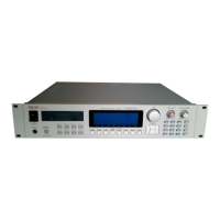
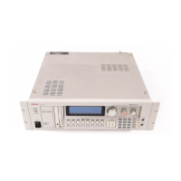
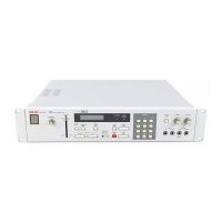
Identification and description of front panel controls.
Diagrams showing the placement of major internal components.
Instructions for changing the unit's voltage settings.
Step-by-step procedures for AM tuner adjustments.
Procedures for adjusting the LW tuner section (AT-S55L only).
Procedures for adjusting the FM tuner section.
Lists P.C. board titles and their corresponding part numbers.
Component layout for AT-S55 P.C. boards.
Component layout for AT-S55L P.C. boards.
Technical specs for the power amplifier section.
Technical specs for the pre-amplifier section.
Power requirements, dimensions, and weight.
Step-by-step instructions for disassembling the unit.
Identification of controls on the AM-U55 model.
Identification of controls on the AM-U55J model.
Diagrams showing component placement for AM-U55.
Diagrams showing component placement for AM-U55J.
Instructions for changing the unit's voltage settings.
Adjustment points on the pre-amplifier circuit board.
Adjustment points on the main amplifier circuit board.
Procedure to adjust the power meter sensitivity.
Procedure to adjust the speaker output DC offset voltage.
Lists P.C. board titles and their corresponding part numbers.
Component layout for AM-U55 P.C. boards.
Component layout for AM-U55J P.C. boards.
List of recommended spare parts for the AT-S55/L model.
List of tuner P.C. board components for AT-S55.
List of synthesizer P.C. board components.
List of power supply P.C. board components.
Lists components for assembly stages.
Lists components for the final assembly stage.
List of recommended spare parts for the AM-U55/J model.
List of main amplifier P.C. board components.
List of components for P.C. board group 1.
List of components for P.C. board group 2 (JPN models).
Lists components for assembly stages.
Lists components for the final assembly stage.
Block diagram and pinout for the LA1231N IC.
Block diagram and pinout for the LA1245 IC.
Block diagram and pinout for the LA3380(B) IC.
Transistor array diagram for LB1260.
Transistor array diagram for LB1269.
Block diagram and pinout for the LB1405S IC.
Block diagram and pinout for the LB1409 IC.
Transistor schematic for M5213L.
Transistor schematic for M5214L.
Transistor schematic for STK-2155.
Transistor schematic for STK-3042.
Block diagram for TA7317.
Block diagram for TA7324P.
Block diagram for TA75558S.
Logic gate diagram for TC4069UBP.
Block diagram for TC9125P.
Block diagram for TD6102P.
Transistor schematic for TD62506P.
Schematic diagram for the AT-S55 synthesizer section.
Schematic diagram for the AM-U55J model.
| Model | AT-S55/L |
|---|---|
| Polyphony | 8 voices |
| MIDI | MIDI In/Out/Thru |
| Type | Synthesizer |
| LFO | 1 LFO |
| Memory | 64 |