Do you have a question about the Akai AX60 and is the answer not in the manual?
Confirms specified insulation resistance for safe operation after repair work.
Guidelines for safe and compliant component replacement and handling during maintenance.
Instructions for setting the correct voltage for the equipment based on region.
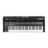
Details the technical features, parameters, and specifications of the AX60 model.
Step-by-step instructions for safely disassembling the AX60 unit's panels and components.
Overview of all front panel controls, buttons, knobs, indicators, and their functions.
Information on keyboard reaction, tempered scale frequencies, and musical notation mapping.
Diagram indicating the physical location of major internal components within the unit.
Detailed steps for calibrating and adjusting various circuit parameters for optimal performance.
List of PC board titles and their corresponding identification numbers for reference.
Defines MIDI message transmission and recognition capabilities for the AX60.
Comprehensive guide to parts, including how to use the list and recommended spares.
Instructions on interpreting part numbers, references, and symbols in the parts list.
List of essential parts recommended for stocking to facilitate efficient repairs.
Listing of parts associated with the main PC board block assembly.
Detailed listing of components for the Voice PC board.
Detailed listing of components for the CPU PC board.
Detailed listing of components for the Chorus PC board.
Detailed listing of components for the Operation (A) PC board.
Detailed listing of components for the Operation (B) PC board.
Detailed listing of components for the Power Supply PC board.
Detailed listing of components for the Filter PC board.
Listing of parts for the Panel Bend block, including wheels and controls.
Listing of parts for general assembly blocks within the unit.
Listing of parts for the final assembly stages of the unit.
Schematic diagram for the power supply PC board.
Diagram illustrating the interconnections between different PCBs and components.
Block diagram showing the control signal flow within the AX60.
Block diagram detailing the voice and chorus signal processing paths.
Schematic representation of the Central Processing Unit (CPU) circuitry.
Diagram showing the layout of components on the CPU PC board.
Diagram showing the layout of components on the Voice PC board.
Diagram illustrating the signal flow for the voice processing section.
Diagram showing the operational control signal flow.
Diagrams showing the layout of components on the Operation (A) and (B) PC boards.
Diagram illustrating the signal flow for the chorus effect.
Diagram showing the layout of components on the Chorus PC board.
Diagram showing the physical location of IC components on the PCBs.
Details ROM IC program changes for improved performance and MIDI functionality.
Information on circuit changes for power supply PC board standardization.
| Type | Analog |
|---|---|
| Polyphony | 6-Voice |
| Oscillators per Voice | 2 |
| Envelope Generator | ADSR |
| Keyboard | 61 Keys |
| Memory | 64 patches |
| MIDI | Yes |
| Year Released | 1986 |
| Waveforms | Sawtooth, Square |
| LFO | Square, Sawtooth |