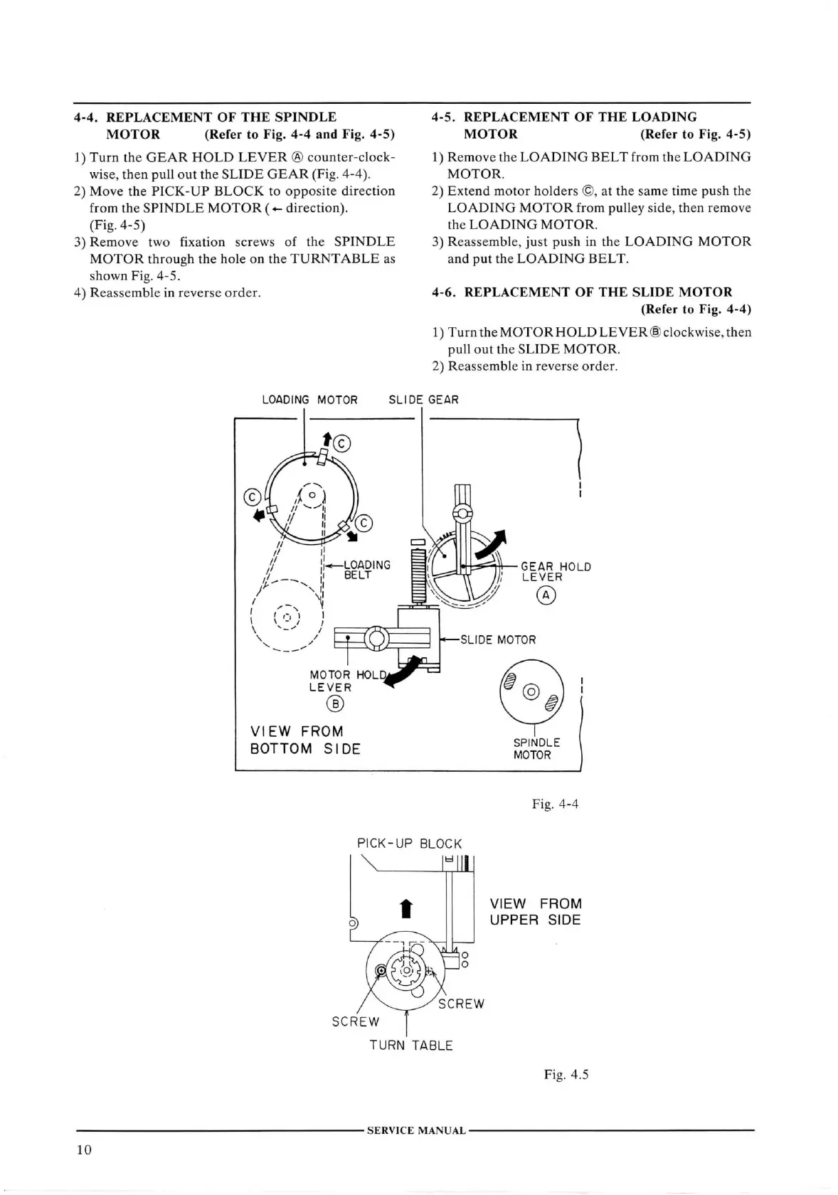
4-4.
REPLACEMENT
OF
THE
SPINDLE
MOTOR
(Refer to Fig. 4-4 and Fig. 4-5)
1)
Turn
the
GEAR
HOLD
LEVER
® counter-clock-
wise,
then
pull
out the
SLIDE
GEAR
(Fig.
4-4).
2)
Move the
PICK-UP
BLOCK
to
opposite
direction
from
the
SPINDLE
MOTOR
(- direction).
(Fig.
4-5)
3)
Remove two fixation screws of the
SPINDLE
MOTOR
through the hole on the
TURNTABLE
as
shown
Fig.
4-5.
4)
Reassemble in reverse order.
4-5.
REPLACEMENT
OF
THE
LOADING
MOTOR
(Refer to Fig. 4-5)
1)
Remove the
LOADING
BELT
from the
LOADING
MOTOR.
2)
Extend
motor holders ©, at the same time push the
LOADING
MOTOR
from pulley side, then remove
the
LOADING
MOTOR.
3)
Reassemble, just push in the
LOADING
MOTOR
and put the
LOADING
BELT.
4-6.
REPLACEMENT
OF
THE
SLIDE
MOTOR
(Refer
to Fig. 4-4)
1)
Turn
the
MOTOR
HOLD
LEVER
(§)
clockwise,
then
pull
out the
SLIDE
MOTOR.
2)
Reassemble in reverse order.
LOADING MOTOR
SLIDE
GEAR
LOADING =
-GEAR
HOLD
LEVER
MOTOR HOL
LEVER
®
VIEW FROM
BOTTOM
SIDE
-SLIDE
MOTOR
@
SPINDLE
MOTOR
Fig.
4-4
PICK-UP
BLOCK zyxwvutsrqponmlkjihgfedcbaZYXWVUTSRQPONMLKJIHGFEDCBA
'"1 1 1
VIEW FROM
UPPER
SIDE
SCREW
SCREV^
TURN
TABLE
Fig.
4.5
SERVICE
MANUAL
10