IV. REPLACEMENT
OF
PICK-UP BLOCK
AND
MOTORS
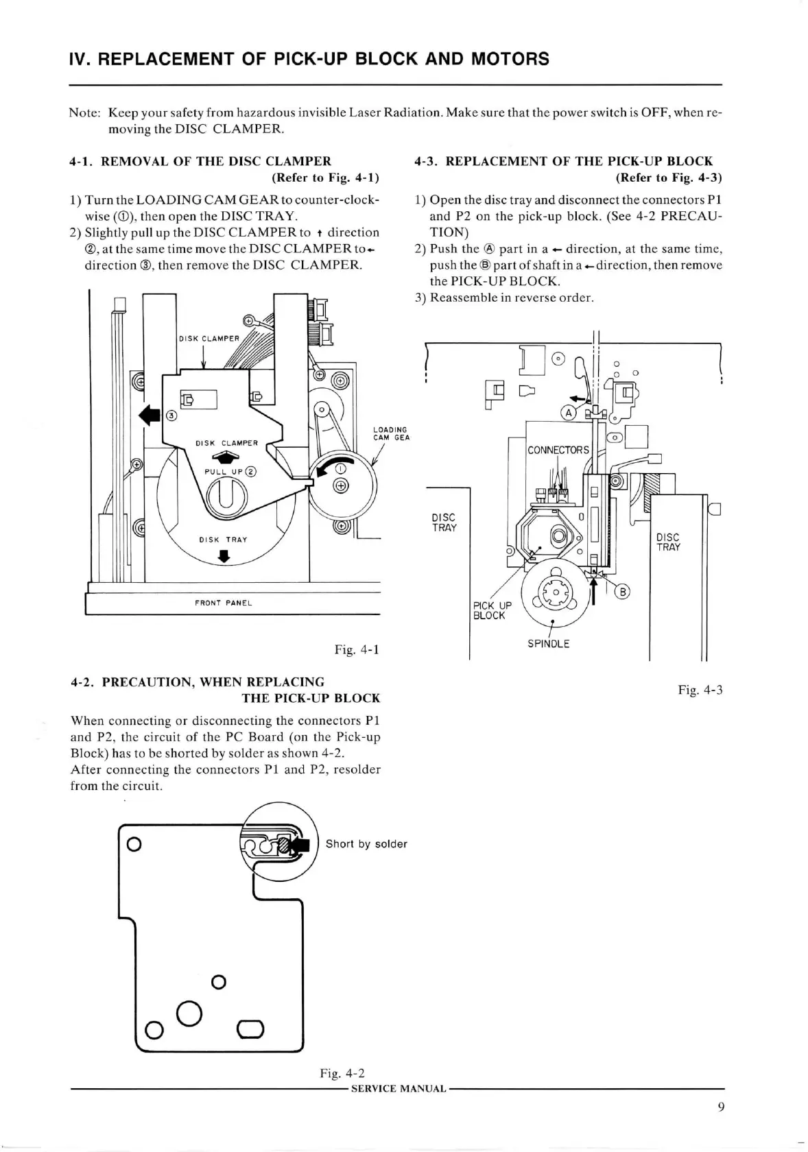
Note: Keep your safety from hazardous
invisible
Laser
Radiation.
Make sure
that
the power
switch
is
OFF,
when re-
movina
the
DISC CLAMPER.
4-1. REMOVAL
OF
THE DISC CLAMPER
(Refer
to Fig. 4-1)
1)
Turn
the
LOADING CAM GEAR
to counter-clock-
wise
(®),
then open the
DISC
TRAY.
2)
Slightly
pull
up the
DISC CLAMPER
to t direction
®,
at the same time move the
DISC CLAMPER
to-^
direction
®, then remove the
DISC CLAMPER.
4-3.
REPLACEMENT
OF
THE PICK-UP BLOCK
(Refer
to Fig. 4-3)
1)
Open the disc tray and disconnect the connectors PI
and P2 on the pick-up block. (See 4-2
PRECAU-
TION)
2)
Push the ® part in a direction, at the same time,
push the
@
part of shaft
in
a direction, then remove
the
PICK-UP BLOCK.
3)
Reassemble in reverse order.
FRONT
PANEL
Fig.
4-1
4-2.
PRECAUTION,
WHEN
REPLACING
THE
PICK-UP BLOCK
When
connecting or disconnecting the connectors PI
and P2, the
circuit
of the PC
Board
(on the Pick-up
Block)
has to be shorted by solder as shown 4-2.
After
connecting the connectors PI and P2, resolder
from
the
circuit.
Fig.
4-3
O
Short
by
solder
O
O
Fig.
4-2
SERVICE
MANUAL-
9