Do you have a question about the Akai CS-MO1A and is the answer not in the manual?
Specifies the track and channel configuration.
Details the type of tape used.
Indicates the tape speed in cm/s and ips.
Lists the types of heads used for recording/playback.
Describes the type of motor and its control.
Specifies the acceptable limits for wow and flutter.
States the time to wind a C-60 cassette.
Outlines the frequency response for different tape types.
Details the signal-to-noise ratio for tape types.
Lists distortion levels for different tape types.
Specifies input levels, impedances, and microphone impedance.
Details output levels and load impedance.
Provides DIN standard input/output specifications.
Lists the physical dimensions of the unit.
States the unit's weight.
Lists voltage and frequency requirements for different regions.
Indicates power consumption in Watts.
Adjustment for playback output level.
Calibration of VU meter response.
Setting the bias oscillator frequency.
Adjusting recording peaking response.
Setting frequency response for Normal tape.
Setting frequency response for CrO2 tape.
Setting frequency response for Metal tape.
Adjusting the recording input level.
Verifying distortion levels after adjustments.
Adjustment for the bias filter circuit.
Tuning the 19 kHz filter.
DC resistance of the record/playback head.
DC resistance of the erase head.
Components on the pre-amp board.
Components on the REC LED board.
Components on the Dolby LED board.
Components on the volume control board.
Components on the lamp board.
List of parts for the head block assembly.
List of parts for the mecha block assembly.
List of parts for the pre-amp board.
List of parts for the front panel.
List of parts for the final assembly.
Overall schematic diagram for CS-M01A.
First step in dismantling the unit.
Second step in dismantling the unit.
Third step in dismantling the unit.
Fourth step in dismantling the unit.
Fifth step in dismantling the unit.
Sixth step in dismantling the unit.
Seventh step in dismantling the unit.
The main power on/off switch.
Slot for inserting cassette tapes.
Switch for timer-based operation.
Controls for the tape counter and reset function.
Displays audio levels during recording/playback.
Light indicating recording status.
Adjusts recording levels for left and right channels.
Inputs for connecting microphones.
Controls for Dolby noise reduction and MPX filter.
Selects tape type (Normal, CrO2, Metal).
Output for connecting headphones.
Keys for playback, stop, fast forward, etc.
Audio outputs for connecting to amplifiers.
DIN standard audio input/output connector.
Audio inputs for connecting external sources.
Selects the audio input source.
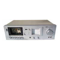
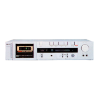
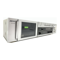
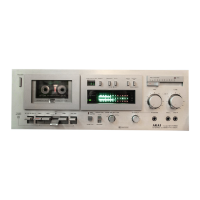
Identifies major components visible from the front.
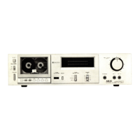
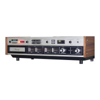
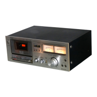
Identifies major components visible from the top.
Procedure for changing the unit's voltage setting.
Information on cycle conversion (not applicable for DC motor).
Detailed explanation of timer start switch functionality.
Explanation of how auto-stop mechanism parts function.
Detailed breakdown of auto-stop operation during playback.
Adjusting the mute leaf switch position.
Adjusting the flywheel's free play.
Measuring the pinch roller pressure.
Measuring winding torque for different modes.
Adjusting the tape transport speed.
Aligning the azimuth of the record/playback head.
Adjusting playback output level on the pre-amp board.
Adjusting VU meter sensitivity on the pre-amp board.
Setting bias oscillator frequency on the pre-amp board.
Adjusting recording peaking on the pre-amp board.
Adjusting frequency response on the pre-amp board.
Diagram showing instrument connections for adjustments.
Specific setup for record peaking adjustment.
Adjustment for playback output level.
Calibration of VU meter response.
Setting the bias oscillator frequency.
Adjusting recording peaking response.
Setting frequency response for Normal tape.
Verifying frequency response for CrO2/FeCr tapes.
Adjusting the recording input level.
Verifying distortion levels after adjustments.
Tuning the 19 kHz filter.
DC resistance of the record/playback head.
DC resistance of the erase head.
List of PC board titles and their numbers.
Details components on various PC boards.
Schematic for Power Switch PC Board (B).
Schematic for Power Switch PC Board (A).
Schematic for Power Switch PC Board (C).
Pre Amp P.C Board Comp. CS-M01 (JPN).
Pre Amp P.C Board Comp. CS-M01 (U/T).
Pre Amp P.C Board Comp. CS-MOI (AAL).
Pre Amp P.C Board Comp. CS-M01 (CSA).
Head BLK CS-M01.
Pinch Roller BLK GX-M10.
Motor BLK GX-M10.
Supply Reel Table BLK.
Take-up Reel Table BLK.
Power Trans. CET-31.
Power Trans. CET-32.
Power Trans. CET-33.
Power Trans. CET-34.
Power Trans. CET-35.
Power Trans. CET-36.
Germanium Diode 1K34A-LR.
LED SEL-1120R.
LED SEL-1320G.
Silicon Diode W03B.
Silicon Diode 1S2473.
Silicon Diode 1S2473 VE.
Zener Diode HZ16-3.
Fuse 1A 125V.
Fuse 1A 250V.
Fuse (Semko T) 1AT.
IC NE545B.
DIN, Pin Jack 4P.
Head Phone Jack HLJ0315-01-020.
Jack HLJ0345-01-010.
Pin Jack 4P.
Lamp (Fuse Type) 8V 55MA.
VU Meter KL-270U-1.
VU Meter KL-270U-2.
Ferri Inductor FE-001 3.3ΜΗ.
OSC Coil OSM-003.
Trap Coil 7AAP-0316.
Dolby Filter D07-001.
Fuse/R. F 1/4W 10 ohms (G).
Fuse/R. 1/4W 56 ohms (J).
Push SW. SDGIP (JPN).
Push SW. SDG1P-E 5A/80A 250V.
Leaf SW. BSW-1F TX-2.
Leaf SW. BUW-31PLC.
Lever SW. 63349.
Lever SW. 83157.
Slide SW. SSC22LP.
Slide SW. 122074.
FET 2SK68 (L) (M).
Transistor 2SC1312S (G) (H).
Transistor 2SC1384 (Q).
Transistor 2SC945L (Q).
Transistor 2SC945L (Q) (P).
Transistor 2SD794 (P) (Q).
Double-Axial 2-Throw/vol. DM80R 50kAx2.
Semi-Fixed/Vol. D10 Axial 100kB.
Semi-Fixed/Vol. D8 Axial 5kB.
Semi-Fixed/Vol. D8 Axial 50kB.
Semi-Fixed/Vol. D8 Axial 10kB.
AC Cord (JPN).
AC Cord (U/T).
AC Cord BASEC.
AC Cord CUL.
AC Cord EC.
AC Cord SAA.
Erase Head E-621.
REC/PB Head RP-2442.
AS Belt.
Capstan Belt.
Counter Belt.
Counter MP390-384.
Counter MP390-385.
Flywheel Part GX-M10.
AS Arm Assy.
List of parts for the head block assembly.
Parts list for the pinch roller block.
Parts list for the mecha block.
Parts list for the motor block.
Parts list for the mecha block assembly.
Chassis Part GX-M10.
Coil Spring T1-3.2/0.2-16.0.
Stop Spring.
Coil Spring T1-3.2/0.29-11.2.
Coil Spring T2-3.2/0.29-11.2.
Pause Spring.
Lock Cam.
Button Lock Spring (B).
Cap.
Supply Reel Table BLK.
Washer (Polyslider) D2.1×4×0.13t.
BT Washer.
BT Spring.
Reel Cap.
Take-up Reel Table BLK.
Release Lever.
Clip (CS Type) CSTW-2.
AS Arm Assy.
Washer (Polyslider) D2.1×4×0.25t.
Push Washer.
Steel Ball D3.
Hold Spring.
Special Tapping Screw, Pan 3x6.
'E' Ring 3M.
Timer Spring.
Counter MP390-384.
Counter MP390-385 (BL).
Screw, Countersunk 3×6.
Counter Beit.
P-Tight Screw, BR 3x8.
Leaf SW. BUW-31PLC.
B-Tight Screw, Pan 2x6.
Lamp (Fuse Type) 8V 55mA.
Key Board Knob (A).
Key Board Knob (A-BL).
Key Board Knob (D).
Key Board Knob (D-BL).
Key Board Knob (B).
Key Board Knob (B-BL).
Key Board Knob (C).
Key Board Knob (C-BL).
Key Board Spring (A).
Key Board Spring (B).
'E' Ring 4M.
Relay Lever Spring.
Cassette Holder.
Brake Shoe.
Brake Spring.
Coil Spring T2-3.2/0.29-14.
Washer (Polyslider) D6.2×13×0.25t.
Middle Gear BLK.
Gear Return Spring.
Washer (Polyslider) D3.1×8×0.25t.
Retaining Ring CS Type 3.
Take-up Idler BLK.
Coil Spring T1-3.2/0.2-8.0.
Key Board Cam.
PB Cam.
Coil Spring T2-3.2/0.2-10.0.
Key Board Cam Spring.
Worm Gear Part GX-M10.
Washer (Polyslider) D2.1×4×0.5t.
Warm Pulley.
AS Belt.
Coil Spring T2-3.2/0.2-12.5.
Pre Amp P.C Board Comp. CS-M01 (U/T).
Pre Amp P.C Board Comp. CS-M01 (JPN).
Pre Amp P.C Board Comp. CS-M01 (CSA).
Pre Amp P.C Board Comp. CS-M01 (AAL).
IC NE545B.
Transistor 2SC1312S(G)(H).
Transistor 2SC945L(Q).
Transistor 2SC945L(Q) (P).
FET 2SK68(L)(M).
Transistor 2SC1384(Q).
Transistor 2SC945L(Q)(P).
Transistor 2SD794(P)(Q).
Transistor 2SD794(P)(Q).
Germanium Diode 1 K34-LR.
Silicon Diode 1S2473.
Silicon Diode W03B.
Zener Diode HZ16-3.
Silicon Diode 1S2473 VE.
Slide SW. 122074.
Lever SW. 63349.
Lever SW. 83157.
Slide SW. SSC22LP.
Semi-Fixed/Vol. D8 Axial 50kB.
Semi-Fixed/Vol. D8 Axial 5kB.
Semi-Fixed/Vol. D8 Axial 10kB.
Semi-Fixed/Vol. D10 100kB.
Ferri Inductor FE-001 3.3MH.
OSC Coil OSM-003.
Dolby Filter D07-001.
Trap Coil 7A AP-0316.
Jack HLJ0345-01-010.
Head Phone Jack HLJ0315-01-020.
DIN, Pin Jack 4P.
Pin Jack 4P (JPN, AAL).
Fuse/R. 1/4W 56 ohms(J).
Fuse/R. F 1/4W 10 ohms (G).
Metal Oxide Film/R. 2W 15 ohms(J).
Styrol/C. 470PF(J) 50WV.
Styrol/C. 200PF(J) 50WV.
Polypropylene/C. 0.0022µF(J) 630WV.
Styrol/C. (Vert.) 200PF(J) 50WV.
Nylon Rivet 4x5.
Screw, Pan 3x8.
Nut, #1 M3.
Parts for Power Switch PC Board (A).
Parts for Power Switch PC Board (B).
Parts for Power Switch PC Board (C).
Parts for the connector base block.
Parts for the amplifier chassis block.
Parts list for the front panel block.
Parts list for the final assembly block.
Schematic diagram for integrated circuits.
Overall schematic diagram for the CS-M01.
Detailed schematic of the NE545B IC.
| Track System | 4-track, 2-channel stereo |
|---|---|
| Tape Speed | 4.76 cm/s |
| Total Harmonic Distortion | 1.0% |
| Motor | DC servo motor |
| Tape Type | CrO2 |
| Frequency Response | 30 Hz - 16 kHz (Metal tape) |
| Signal to Noise Ratio | 58dB (dolby B) |