Do you have a question about the Akai CS-F110 and is the answer not in the manual?
Confirms insulation resistance of the set for safety after repairs.
Lists critical safety precautions and procedures for servicing the equipment.
Details tape system, frequency response, noise ratio, input/output, and power requirements.
Provides step-by-step visual guide for disassembling the unit in a specific order.
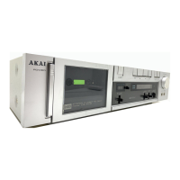
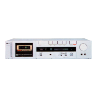
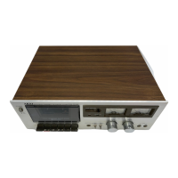
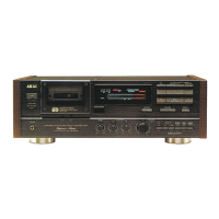
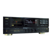
Identifies front, rear, and side panel controls and connections for CS-F110/CS-F12 models.
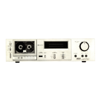
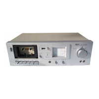
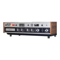
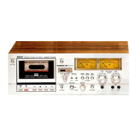
Identifies front, rear, and side panel controls and connections for CS-F210/J models.
Locates and labels key components visible from the front and top of the CS-F110/CS-F12 unit.
Locates and labels key components visible from the front and top of the CS-F210/J unit.
Instructions for voltage conversion and notes on cycle conversion for DC motor units.
Specifies torque meter usage and tape speed adjustment procedures.
Describes the process for aligning the REC/Playback head azimuth using an alignment test tape.
Identifies adjustment points, instruments connection, and bias oscillation prevention.
Details steps, items, test signals, parts, results, and remarks for amplifier adjustments.
Lists DC resistance values for REC/PB Head, Erase Head, and Solenoids.
Provides a list of P.C. board titles and their corresponding identification numbers.
Details the composition of Pre Amp, Volume, and Detector P.C. boards for the CS-F110 model.
Details the composition of Pre Amp, Volume, and Detector P.C. boards for the CS-F12 model.
Details the composition of Pre Amp, Volume, and Detector P.C. boards for the CS-F210 model.
Details the composition of Pre Amp, Volume, and Detector P.C. boards for the CS-F210J model.
Details wiring and component layout for Operation and Meter P.C. boards.
Illustrates component layout and wiring for Power Supply P.C. boards in various models.
Provides instructions on interpreting reference numbers, parts numbers, and descriptions in the parts list.
Lists recommended spare parts for the CS-F110/F12 model to facilitate repairs.
Details parts for the mecha block assembly of the CS-F110/F12 model.
Lists parts for P.C. boards, assembly, and final assembly blocks.
Lists recommended spare parts for the CS-F210 model to facilitate repairs.
Details parts for the mecha block assembly of the CS-F210 model.
Lists parts for P.C. boards, assembly, and final assembly blocks.
Provides schematic diagrams for ICs HA12019 and LM1111C.
Shows schematics for TA78L008AP, TC4049BP, TC4011BP, and TK11002 ICs.
Presents the complete schematic diagram for the CS-F110 model.
Presents the complete schematic diagram for the CS-F12 model.
Presents the complete schematic diagram for the CS-F210J model.
Presents the complete schematic diagram for the CS-F210 model.
| Track System | 4-track, 2-channel stereo |
|---|---|
| Tape Speed | 4.76 cm/s |
| Frequency Response | 30Hz to 16kHz (Metal tape) |
| Wow and Flutter | 0.06% WRMS |
| Type | Cassette Deck |
| Heads | 2 |
| Motor | 1 x DC motor |
| Tape Type | Type I, CrO2, Metal |
| Signal to Noise Ratio | 58dB (dolby B) |
| Power Supply | 220V, 50Hz |
| Inputs | Line In |
| Outputs | Line out |