Do you have a question about the Akai CS-F14 and is the answer not in the manual?
Checks to perform post-repair to ensure safety and proper functionality.
Guidelines for safe maintenance procedures, including part replacement and wiring.
Technical details and performance data of the unit, including track system and frequency response.
Step-by-step instructions for disassembling the device for repair or maintenance.
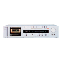
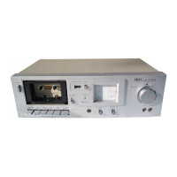
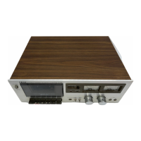
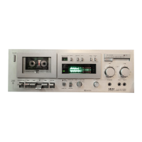
Identification and function of front and rear panel controls for the CS-F14 model.
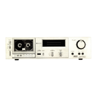
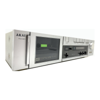
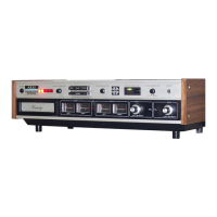
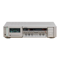
Identification and function of front and rear panel controls for the CS-F21 model.
Identification of major components within the CS-F14 unit chassis.
Identification of major components within the CS-F21 unit chassis.
Procedures for adjusting power supply voltage and cycle settings for different regions.
Procedures for adjusting mechanical parts like torque and tape speed, and head alignment.
Procedures for calibrating audio amplifier circuits and performance settings.
Resistance values for various coils, including heads and solenoids.
Listing and identification of printed circuit boards used in the unit.
Guide on interpreting and using the parts catalog, including reference numbers and classifications.
Recommended spare parts, mecha block, and PCB parts lists for the CS-F14 model.
Recommended spare parts, mecha block, and PCB parts lists for the CS-F21 model.
Alphabetical listing of parts for quick reference by part number.
Circuit diagrams for integrated circuits (ICs) used in the unit.
Complete circuit diagram for the CS-F14 model.
Complete circuit diagram for the CS-F21 model.
| Track System | 4-track, 2-channel stereo |
|---|---|
| Tape Speed | 4.76 cm/s |
| Heads | 1 x record/playback, 1 x erase |
| Total Harmonic Distortion | 1.0% |
| Channels | 2 |
| Type | Stereo Cassette Deck |
| Motor | DC servo |
| Tape Type | CrO2 |
| Signal to Noise Ratio | 58dB (dolby B) |
| Wow and Flutter | 0.06% |
| Input | 70mV (line) |
| Inputs | Line in |
| Outputs | Line out |
| Power Supply | 220V, 50Hz |