Do you have a question about the Akai GX-52 and is the answer not in the manual?
| Brand | Akai |
|---|---|
| Model | GX-52 |
| Category | Cassette Player |
| Language | English |
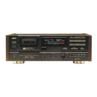
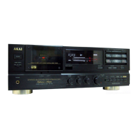
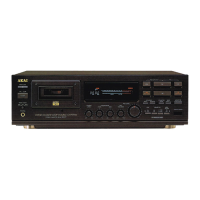
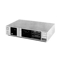
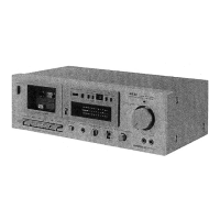
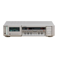
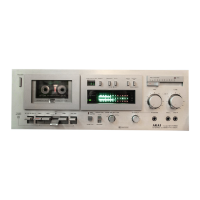
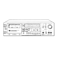
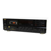
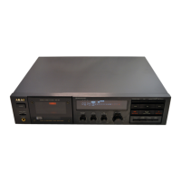
Technical specifications for the Akai GX-52 stereo cassette deck.
Safety guidelines before, during, and after servicing.
Steps for removing the upper and front covers.
Description of front panel buttons, knobs, and displays.
Diagram showing the location of principal parts from the top.
Procedures for pinch roller pressure and winding torque measurement.
Step-by-step guide for installing volume control and cam wheel.
Procedures for Rec/Pb Head Projection, Tape Guide Height, and Azimuth alignment.
Adjusting the vertical alignment of the record/playback head.
Adjusting meter sensitivity, tape speed, and frequency response.
Adjusting bias point, bias frequency, playback, and recording levels.
Guide on using the parts list, ordering notes, and safety warnings.
List of recommended spare parts for stocking and maintenance.
Detailed parts list for the mecha block assembly.
Information on which parts are normally stocked for replacement.
Parts list for the BLM-300 motor block.
Information on parts availability for routine service.
Lists of components and parts on the Pre Amp and Head Phone PCBs.
Lists of components and parts on System Control (1) and (2) PCBs.
Component lists for Timer, Remocon, and Motor PCBs.
Diagram of the final assembly with part references.
Explanation of color coding symbols used in diagrams.
Explanations of abbreviations used throughout the service manual.
List of schematic sections and their corresponding page numbers.
Diagrams and component layouts for Head Phone, Power Trans, Timer SW, Remocon PCBs.
Safety critical component warning.
Diagrams showing component locations on System Control (1) and (2) PCBs.
Wiring diagrams for various PCBs and power transformer connections.
Notes on default component values and specifications.
Diagrams showing component locations on System Control (1) and (2) PCBs.
Schematic diagrams for Motor, Potention, and FG PCBs.
Internal block diagrams for specific integrated circuits.
Location and identification of components on System Control PCBs.
Functional block diagrams of integrated circuits.
Diagram indicating component placement on the PCB.
Schematic diagram for the Pre Amp PCB, including safety and specification notes.
Location and identification of components on the Pre Amp PCB.
Safety critical component warning.
Block diagrams of mecha, control, and integrated circuit functions.