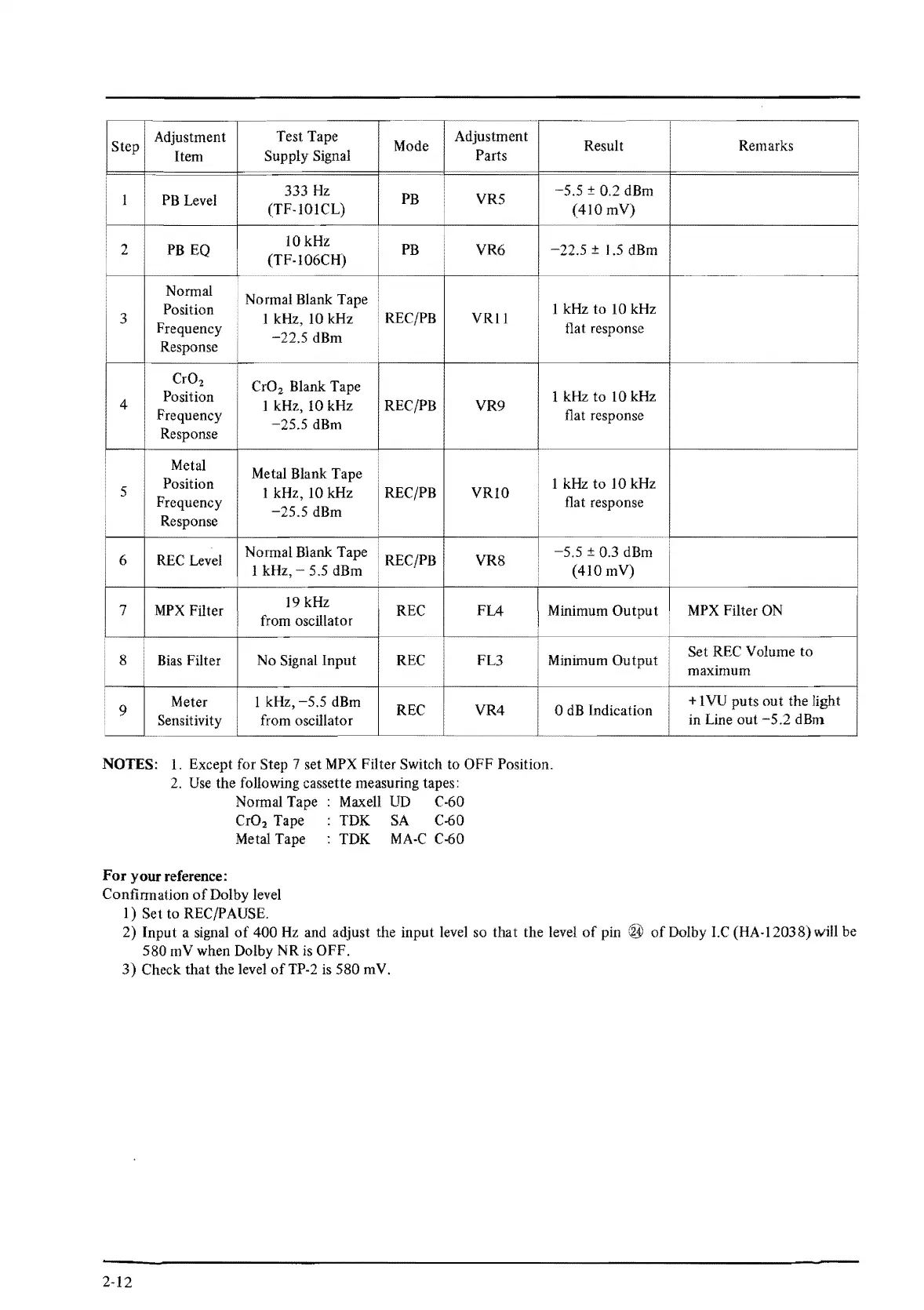
Step
Adjustment
Test Tape
Mode
Adjustment
Result
Item
Supply Signal
Parts
I
PB
Level
333
Hz
PB
YRS
-5.5
± 0.2 dBm
(TF-IOICL)
(410
mV)
2
PB
EQ
lOkHz
PB
VR6
-22.5
± 1.5 dBm
(TF-l06CH)
Normal
Normal Blank Tape
Position
1 kHz
to
IO
kHz
3
Frequency
l kHz,
IO
kHz
REC/PB
VRll
flat response
Response
-22.5
dBm
CrO
2
CrO
2
Blank Tape
4
Position
I kHz, 10 kHz
REC/PB
VR9
1 kHz
to
10 kHz
Frequency flat response
Response
-25.5
dBm
Metal
Metal Blank Tape
Position 1 kHz
to
10 kHz
5
Frequency
1 kHz, 10 kHz
REC/PB
VRI0
flat response
Response
-25.5
dBm
6
REC Level
Normal Blank Tape
REC/PB
VR8
-5.5
± 0.3 dBm
1 kHz, - 5.5 dBm (410 mV)
:
7
MPX
Filter
19 kHz
REC
FL4
I Minimum
Output
from oscillator
8 Bias Filter No Signal
Input
REC FL3 Minimum
Output
9
Meter
I kHz,
-5.5
dBm
REC
VR4
0
dB
Indication
Sensitivity from oscillator
NOTES: 1. Except for Step 7 set MPX Filter Switch to
OFF
Position.
2.
Use
the following cassette measuring tapes:
Normal Tape Maxell UD C-60
CrO
2
Tape TDK SA C-60
Metal Tape TDK
MA-C
C-60
For
your reference:
Confirmation
of
Dolby level
I)
Set
to
REC/PAUSE.
Remarks
MPX Filter ON
Set
REC Volume
to
maximum
+ 1 VU
puts
out
the light
in Line
out
-5.2
dBm
2)
Input
a signal
of
400
Hz
and adjust the input level so
that
the level
of
pin
580
mV
when Dolby NR is
OFF.
of
Dolby
LC
(HA-12038) will be
3)
Check
that
the level
ofTP-2
is
580
mV.
2-12
 Loading...