Do you have a question about the Akai M-10 and is the answer not in the manual?
Details tape speed, wow/flutter, frequency response, S/N ratio, distortion, and crosstalk.
Information on power supply, motors, heads, and input/output specifications.
Lists transistors, ICs, and diodes used in the device.
Method to measure tape speed deviation using pre-recorded or timing tape.
Procedure for measuring wow and flutter levels.
Steps for measuring the frequency response during record and playback.
Method to measure the total harmonic distortion of the unit.
Procedure for measuring the signal to noise ratio.
Method for measuring crosstalk between tracks on the tape.
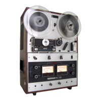
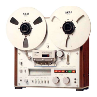
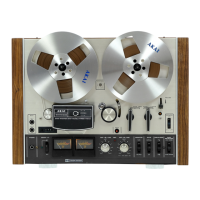
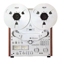
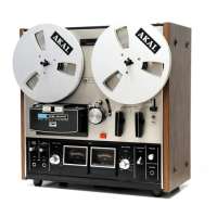
Identification and location of front panel controls and indicators.
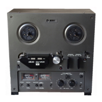
Location of rear panel connectors and other access points.
Step-by-step guide for dismantling the tape transport mechanism.
Visual guide to back panel and connection points for disassembly.
Specifies voltages for torque motors during operation.
Details the required pinch roller pressure.
Explains the reverse playback function and its circuitry.
Describes the operation of fast forward and rewind modes.
Details the function of the automatic stop mechanism.
Procedure for adjusting the height of playback/record and erase heads.
Method for aligning the azimuth of playback/record and erase heads.
Procedure for adjusting brake tension using a tension gauge.
Steps to adjust the height of the reel table.
Diagrams showing exploded views of motor, switch lever, and flywheel blocks.
Procedure to adjust playback pre-amplifier output level.
Steps for adjusting the recording level.
Adjusting bias frequency, voltage, and DC bias current.
Procedure for adjusting the level control potentiometer VR601.
Guidelines for lubricating mechanical parts for optimal performance.
Instructions for cleaning tape heads, rollers, and other components.
Diagram of the Pre-Amplifier Printed Card (MRA-501).
Diagrams of System Control (MR-504) and OSC (MR-505) Printed Cards.
Diagram of the Main Amplifier Printed Card (MRA-508).
Diagrams of Tone Control, Power Source, and Tension Relay PCBs.
Troubleshooting guide for tape transport mechanism problems.
Troubleshooting for amplifier problems during playback.
Troubleshooting for amplifier problems during recording.
Diagnosing issues like lack of treble, fading, and dropouts.