Do you have a question about the Akai 4000DB and is the answer not in the manual?
Details on track system, reel capacity, tape speed, motor, heads, recording capacity, and transport times.
Measurements for wow/flutter, frequency response, distortion, signal-to-noise, cross-talk, and erase ratio.
Specifies input/output levels, recording/playback levels, bias frequency, and leak.
Lists transistors, ICs, diodes, FETs, power supply details, dimensions, and weight.
Lists DC resistance values for motor, heads, transformers, and oscillator coil.
Procedures for measuring tape speed deviation and wow and flutter.
Methods for measuring frequency response and signal-to-noise ratio.
Techniques for measuring harmonic distortion, cross-talk, and erase ratio.
Instructions for safely disassembling the unit for servicing.
Procedures for setting pinch wheel pressure and reel shaft friction.
Steps for adjusting drive belt position and flywheel loose play.
Instructions for idler position, auto shut-off, and shifter lever settings.
Procedures for adjusting the vertical position of erase, record, and playback heads.
Steps for aligning the horizontal angle of playback and record heads.
Initial setup, prior adjustments, and instrument connection for amplifier calibration.
Adjusting resistors, capacitors, and signal levels in the amplifier system.
Adjusting frequency response and checking recording bias.
Steps for calibrating the Dolby NR recording circuit.
Procedure to verify the Dolby NR playback circuit performance.
Description of the Dolby NR circuit's operation during recording.
Description of the Dolby NR circuit's operation during playback.
Composite illustrations and part lists for main printed circuit boards.
Illustration and parts list for the Pre-Amplifier PC Board.
Illustration and parts list for the Dolby Noise Reduction PC Board.
Illustration and parts list for the Oscillator and Power Supply PC Board.
Guide on how to read and use the parts list and electrical components table.
Table showing shapes and names of various resistors and capacitors used.
Exploded view illustration of the Head Block assembly.
List of parts for the Head Block assembly.
List of parts for the Reel Table Block assembly.
List of parts for the Motor Block assembly.
List of parts for the Flywheel and Belt Change Lever Block.
List of parts for the Switch Block assembly.
List of parts for the Mechanical Assembly Block.
Continuation of the parts list for the Mechanical Assembly Block.
List of parts for the Pre-Amplifier PC Board.
Photograph of the Pre-Amplifier PC Board with component labels.
List of parts for the Oscillator and Power Supply PC Board.
Photograph of the Dolby PC Board with component labels.
List of parts for the Dolby PC Board.
List of parts for the Amplifier Assembly Block.
List of parts for the Power Supply Frame Block.
List of parts for the Jack Plate Block.
List of parts for the Amplifier Chassis Block.
List of parts for the Final Assembly Block.
The overall circuit diagram for the AKAI 4000DB stereo tape deck.
| Track System | 4-track, 2-channel, stereo/monaural system |
|---|---|
| Wow and Flutter | 0.08% (7 1/2 ips) |
| Signal to Noise Ratio | 58dB |
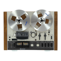
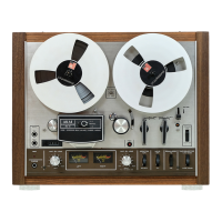
| Type | Reel-to-reel tape deck |
| Tape Speed | 3 3/4 & 7 1/2 ips |
| Heads | 1 x erase |
| Frequency Response | 30Hz to 22kHz (7 1/2 ips) |
| Inputs | Microphone, Line |
| Outputs | Line, Headphones |