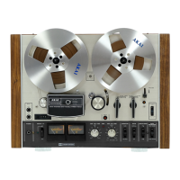
Do you have a question about the Akai 4000DS and is the answer not in the manual?
Procedures for testing and verifying tape deck performance parameters.
Instructions for calibrating and adjusting mechanical components of the tape deck.
Procedures for aligning and adjusting the tape heads for optimal performance.
Steps for calibrating and tuning the audio amplifier circuits.
Method for measuring and verifying the accuracy of tape transport speed.
Techniques for measuring tape speed variations affecting sound quality.
Procedure to test the audio frequency range reproduction capability.
Method for measuring the difference between signal and noise levels.
Procedure for measuring unwanted harmonic distortion in audio signals.
Method for measuring signal leakage between audio tracks.
Procedure to measure the effectiveness of the tape erase function.
Procedure for correctly setting the pinch wheel pressure and alignment.
Adjusting the supply reel tension and slippage for proper tape handling.
Adjusting the take-up reel tension and slippage for controlled tape winding.
Adjusting the mechanism that switches between recording and playback modes.
Procedure for setting the vertical position of the erase, recording, and playback heads.
Method for ensuring tape heads are perpendicular to the tape path.
Procedure for aligning the tape heads horizontally for optimal signal playback.
Calibrating the playback amplifier output levels for accurate audio reproduction.
Setting the recording amplifier input and output levels for optimal recording.
Adjusting the bias oscillator frequency for correct tape recording.
Tuning bias voltage to optimize the frequency response during recording.
| Track System | 4-track, 2-channel, stereo/monaural system |
|---|---|
| Reel Size | Up to 7 inch reel |
| Signal to Noise Ratio | 50dB |
| Total Harmonic Distortion | 1.5% |
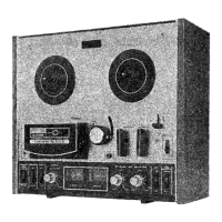
| Type | Reel to Reel tape deck |
| Heads | 1 x record, 1 x playback, 1 x erase |
| Tape Speeds | 3 3/4 ips, 7 1/2 ips |
| Wow and Flutter | 0.08% (7.5 ips) |
| Inputs | Mic, Line |
| Outputs | Line |
| Semiconductors | 4 x diodes |