Do you have a question about the Akai 4000 DS-Mk2 and is the answer not in the manual?
Detailed technical performance parameters and characteristics of the tape deck.
Procedures and diagrams for testing key performance metrics like tape speed and frequency response.
Step-by-step visual guide for disassembling internal components and units.
Instructions and diagrams for calibrating mechanical parts to ensure proper operation.
Procedures for aligning and adjusting tape heads for optimal recording and playback quality.
Steps to adjust audio amplifier levels and bias for accurate sound reproduction.
Visual representations of internal circuit boards and component layouts.
Guide explaining how to read and interpret part numbers and diagrams in the list.
Exploded view and part list for the tape head assembly.
Exploded view and part list for the reel table and drive mechanisms.
Exploded view and part list for the motor assembly.
Exploded view and part list for the flywheel, belt, and lever mechanisms.
Exploded view and part list for the various switches and their mechanisms.
Exploded view and part list for the overall mechanism assembly.
Photograph and part identification for the pre-amplifier circuit board.
Photograph and part identification for the oscillator and power supply circuit board.
Photograph and part list for the amplifier assembly.
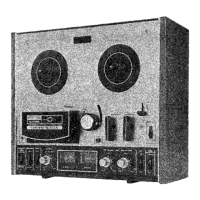
Photograph and part list for the complete final assembly of the tape deck.