Do you have a question about the Akai GX-4000D and is the answer not in the manual?
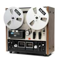
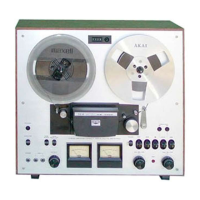
Detailed specifications for GX-4000D and GX-4000DB models.
Step-by-step guide for disassembling the tape deck unit.
Identification and description of all operational controls on the tape deck.
Diagrams showing the location of key components within the unit.
Procedures for adjusting various mechanical parts for optimal performance.
Procedure to measure and set the correct pinch roller pressure.
Adjusting reel table tension and free play for proper tape handling.
Ensuring the drive belt is correctly positioned on the motor pulley.
Adjusting the flywheel to eliminate loose play and ensure smooth operation.
Setting the operating point for the automatic tape shut-off mechanism.
Procedures for aligning and adjusting the record, playback, and erase heads.
Adjusting the vertical position of the heads relative to the tape.
Aligning the head gap perpendicular to the tape path for optimal playback.
Adjusting the head tilt angle for proper tape contact.
Calibration steps for the amplifier circuits for both models.
Specific adjustment steps for the GX-4000D amplifier section.
Specific adjustment steps for the GX-4000DB amplifier section.
Table listing the DC resistance values for various coils in the unit.
Lists P.C. board titles and their corresponding identification numbers.
Guide on how to interpret and use the parts list effectively.
Details on the AC inlet system and power cord compatibility.
List of essential spare parts recommended for stocking.
Diagram showing parts for the head base block assembly.
Diagram showing parts for the motor block assembly (IMC-100).
Diagram showing parts for the reel table block assembly.
Diagram showing parts for the flywheel block assembly.
Diagram showing parts for the switch block assembly.
Diagram showing parts for the mecha assembly block.
Diagrams illustrating various Printed Circuit Boards.
Diagrams illustrating different versions of the power supply P.C. board.
Diagram showing parts for the power and amplifier assembly.
Diagram showing parts for the final assembly block.
List of substitute semiconductor parts for servicing.
Circuit diagram for the GX-4000D model.
Circuit diagram for the GX-4000DB model.
| Track System | 4-track, 2-channel, stereo/monaural system |
|---|---|
| Reel Size | Up to 7 inch reel |
| Tape Speeds | 3 3⁄4 7 1⁄2 ips |
| Frequency Response | 30Hz to 24kHz (7 1⁄2 ips) |
| Type | Reel to Reel |
| Heads | 1 x erase |
| Motor | 1 x capstan, 1 x reel |
| Wow and Flutter | 0.08% (7.5 ips) |
| Output | 0.775V (line) |
| Input | 70mV (line) |
| Inputs | Line |
| Outputs | Line |