EasyManua.ls Logo

Akai M-7 - Page 11

Akai M-7
19 pages
Print Icon
To Next Page IconTo Next Page
To Previous Page IconTo Previous Page
Loading...
Vl
ADJUSTMENT
OF
AMPLIFIER
1,
ADJUSTMENT
OF
RECORDING
BIAS
FREQUENCY
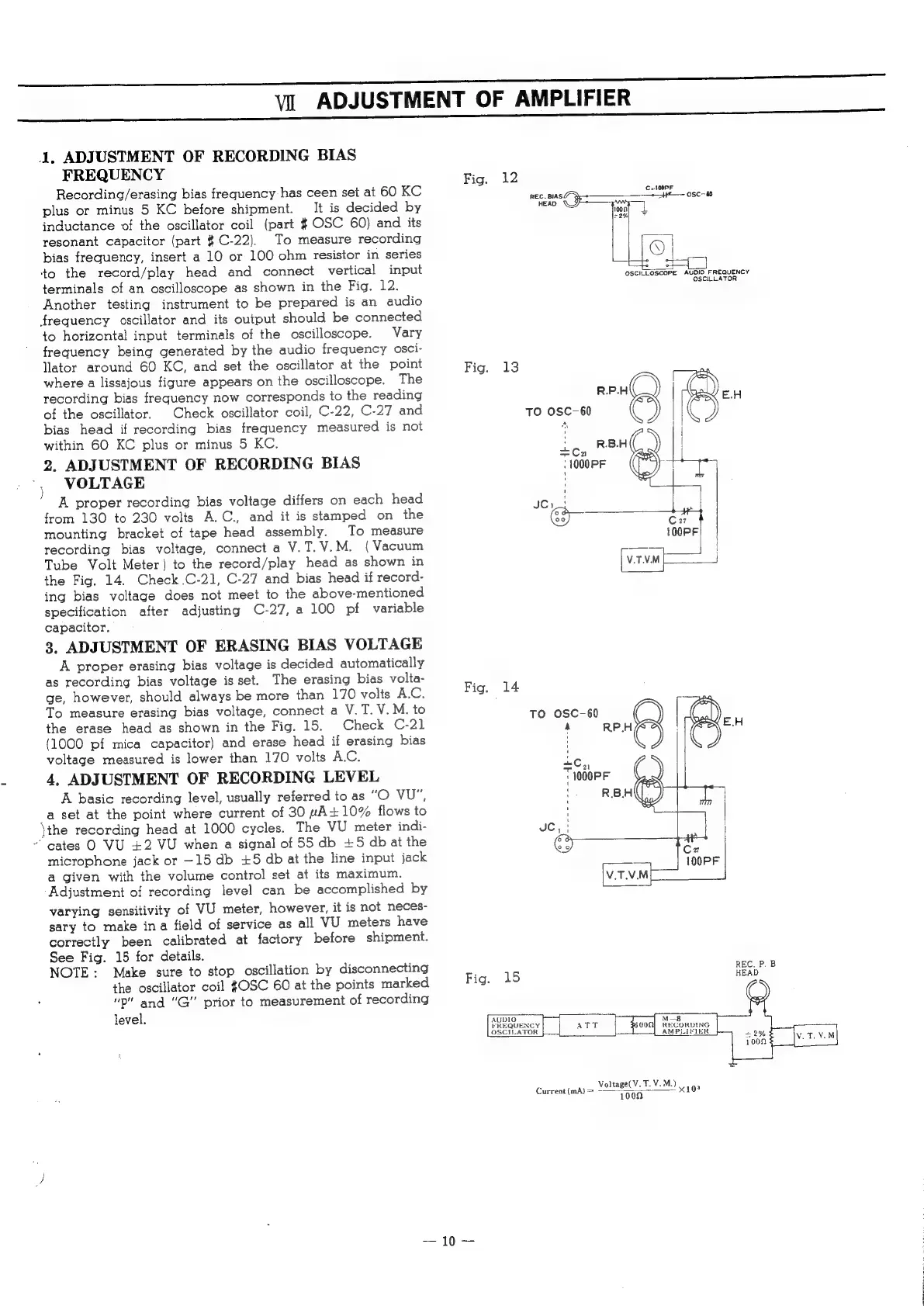
Recording/erasing
bias
frequency
has
ceen
set
at
60
KC
plus
or
minus
5
KC
before
shipment.
It
is
decided
by
inductance
of
the
oscillator
coil
(part
#
OSC
60)
and
its
resonant
capacitor
(part
#
C-22).
To
measure
recording
bias
frequency,
insert
a
10
or
100
ohm
resistor
in
series
‘to
the
record/play
head
and
connect
vertical
input
terminals
of
an
oscilloscope
as
shown
in
the
Fig.
12.
Another
testing
instrument
to
be
prepared
is
an
audio
frequency
oscillator
and
its
output
should
be
connected
to
horizontal
input
terminals
of
the
oscilloscope.
Vary
frequency
being
generated
by
the
audio
frequency
osci-
lator
around
60
KC,
and
set
the
oscillator
at
the
point
where
a
lissajous
figure
appears
on
the
oscilloscope.
The
recording
bias
frequency
now
corresponds
to
the
reading
of
the
oscillator.
Check
oscillator
coil,
C-22,
C-27
and
bias
head
if
recording
bias
frequency
measured
is
not
within
GO
KC
plus
or
minus
5
KC.
2.
ADJUSTMENT
OF
RECORDING
BIAS
VOLTAGE
A
proper
recording
bias
voltage
differs
on
each
head
from
130
to
230
volts
A.C.,
and
it
is
stamped
on
the
mounting
bracket
of
tape
head
assembly.
To
measure
recording
bias
voltage,
connect
a
V.T.V.M.
(Vacuum
Tube
Volt
Meter)
to
the
record/play
head
as
shown
in
the
Fig.
14.
Check
.C-21,
C-27
and
bias
head
if
record-
ing
bias
voltage
does
not
meet
to
the
above-mentioned
specification
after
adjusting
C-27,
a
100
pf
variable
capacitor.
3.
ADJUSTMENT
OF
ERASING
BIAS
VOLTAGE
A
proper
erasing
bias
voltage
is
decided
automatically
as
recording
bias
voltage
is
set.
The
erasing
bias
volta-
ge,
however,
should
always
be
more
than
170
volts
A.C.
To
measure
erasing
bias
voltage,
connect
a
V.T.V.M.
to
the
erase
head
as
shown
in
the
Fig.
15.
Check
C-21
(1000
pf
mica
capacitor)
and
erase
head
if
erasing
bias
voltage
measured
is
lower
than
170
volts
A.C.
4,
ADJUSTMENT
OF
RECORDING
LEVEL
A
basic
recording
level,
usually
referred
to
as
“O
VU",
a
set
at
the
point
where
current
of
30
pA+10%
flows
to
\the
recording
head
at
1000
cycles.
The
VU
meter
indi-
~
cates
O
VU
£2
VU
when
a
signal
of
55
db
+5
db
at
the
microphone
jack
or
—15
db
+5
db
at
the
line
input
jack
a
given
with
the
volume
control
set
at
its
maximum.
Adjustment
of
recording
level
can
be
accomplished
by
varying
sensitivity
of
VU
meter,
however,
it
is
not
neces-
sary
to
make
ina
field
of
service
as
all
VU
meters
have
correctly
been
calibrated
at
factory
before
shipment.
See
Fig.
15
for
details.
NOTE:
Make
sure
to
stop
oscillation
by
disconnecting
the
oscillator
coil
{OSC
60
at
the
points
marked
"p"
and
"G'
prior
to
measurement
of
recording
level.
Fig.
12
C2:
100PF
REC.
BIASY
Sy
tH
osc-60
HEAD
WH
t
1
ee
i
ead
OSCILLOSCOPE
AUDIO
FREQUENCY
OSCILLATOR
Fig.
13
R.P.H
TO
OSC-60
Pa
|
{
:
.B.
|
ic,
RBH
-1000PF
Sea
C13
;
4
C27
100PF
V.T.V.M
Fig.
14
TO
OSC-60
A
RP.H
=C,,
T1000PF
:
R.B.H
JC,
|
|
@)
ten
100PF
V.T.V.M
Fig.
15
AUDIO
ae
M—8
FREQUENCY
At
ds
|
S000
RECORDING
OSCILATOR
AMPLIFIER
.
Voltage(V.
T.
V.
M.)
Current
(mA)
=
-
100n
x10?
E.H