7
FEATURES
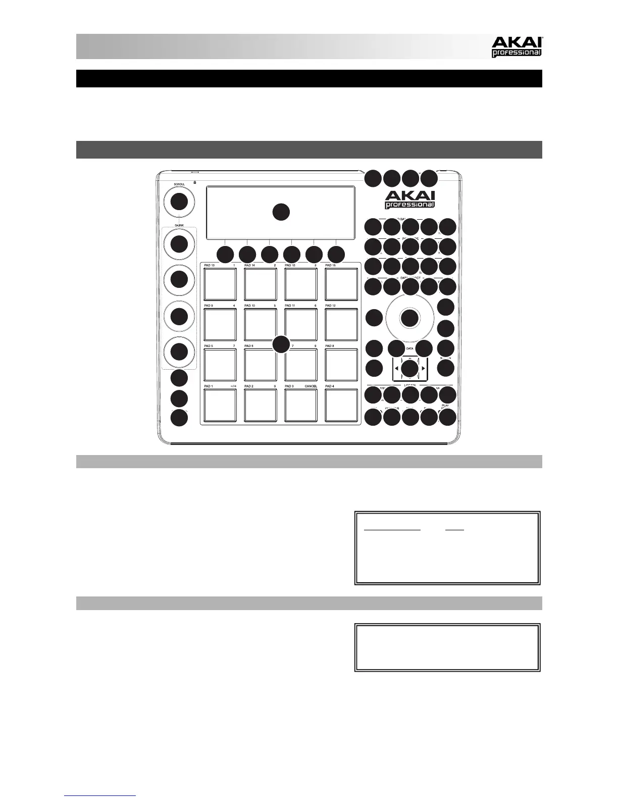
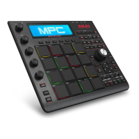
MPC Studio is hardware specifically designed to control the MPC software. This section describes all the
hardware controls. For a complete explanation of the software, please see the MPC Reference Manual in the
software in the Help menu.
TOP PANEL
5
1234
13
12
12
12
12
14
20
46
21
23
32
22
15
16
18
24 25 26 27 28
33 34 35 36 37
41 42 40 38 39
43
47
43 45 44 44
19 29 30 31
16 16 16 17
666666
7
8
10
11
55
POWER & I/O
1. COMPUTER USB PORT– Use the included USB cable to connect this high-retention-force USB port to an
available USB port on your computer. This connection allows MPC Studio to send/receive MIDI and audio
data to/from the MPC software.
2. POWER SWITCH – Turns MPC Studio's power on/off.
3. MIDI IN – Use the included 1/8"-MIDI adapter and a five-
pin MIDI cable to connect the MIDI OUT of an optional
external MIDI device to the MIDI IN of MPC Studio.
4. MIDI OUT – Use the included 1/8"-MIDI adapter and a
five-pin MIDI cable to connect the MIDI OUT of MPC
Studio to the MIDI IN of an optional external device.
NAVIGATION / DATA ENTRY CONTROLS
5. DISPLAY – This LCD shows all the information relevant to
MPC Studio's current operation. Much of this information
is also shown in the software. Use the CURSOR
BUTTONS to navigate through the display, and use the
DATA DIAL, and -/+ buttons to adjust the currently
selected setting/parameter. Use the MODE buttons to
change what page is shown, and use the F-BUTTONS to change what tab is shown.
6. F-BUTTONS – Press one of these buttons to select its corresponding tab, shown above the button in the
display.
7. CURSOR BUTTONS – Use these buttons to navigate through the fields of menus and options shown in the
DISPLAY.
Press and hold SHIFT and turn the DATA
DIAL to adjust the contrast of the
DI
PLAY.
IMPORTANT: Do NOT connect audio
devices (e.g., headphones, monitors,
etc.) to the 1/8" MIDI IN or MIDI OUT
jacks. Use the included 1/8"-MIDI
adapters to connect MIDI devices only.